Telescopic Approach
Contents
- 1 Summary
- 2 Highlights of Findings
- 3 Parallel Data Refinement (PDR)
- 4 CDT3D
- 5 Integration of Loosely Coupled Approach with Tightly Coupled using CDT3D and the Parallel Runtime System (PREMA)
- 6 Integration of error-based anisotropic adaptive (CTD3D) grids with MIT's CFD solver
- 7 Moving Forward to Extreme Scales: Performance Data from up to 16k cores
Summary
The main accomplishments have been:
- Identified and implementation of three mesh generation approaches for the lower chip-level (optimistic) implementation of 3D tetrahedral parallel mesh generation and adaptation:
- Homegrown Parallel Optimistic Delaunay (3D and 4D) mesh generation, referred as PODM
- Use open source sequential software TetGen and sequential AFLR code from former NSF' ERC at MSU
- Develop a new implementation (CDT3D) using known algorithms for anisotropic mesh generation and adaptation, but taking into account lessons learned from and new requirements for ODU’s telescopic approach and
- a completely new method in which an anisotropic 3D metric is embedded and isotropically meshed on a manifold in 4D dimensional space which could leverage ODU’s 4D Delaunay-based parallel optimistic I2M conversion technology. This is work in progress.
- Designed and implemented two out of four layers of the telescopic approach using PODM:
- Completed the Parallel Data Refinement (PDR) layer that targets multiple nodes (within a single rack).
- In progress to develop Parallel Constrained (PC) layer that targets multiple racks of nodes,
- Identified test cases with NASA/LaRC (CAD model of a half DLR-F6 Airbus-type aircraft and a series of complex components from AIM@SHAPE repository) to evaluate mesh generation and adaptation modules.
- Identified two state-of-the-art software runtime systems from industry, academia and national labs that meet the requirements of the proposed Multi-Layered Runtime System (MRTS):
- OCR is a runtime system from Intel and
- Argo is an exascale-era ecosystem build by a collaboration effort between DoE labs (mainly ANL) and academia.
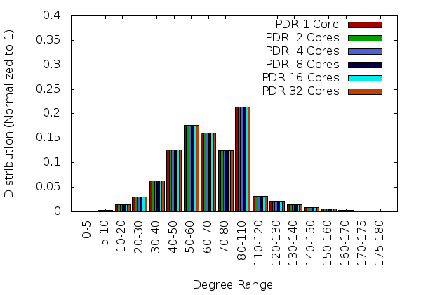
The results so far are promising. For example, the initial PDR implementation using TetGen and PODM methods is stable (i.e., generate the same quality mesh with the sequential code, see Figure 1), robust (i.e., can mesh all the geometries tried –those the sequential code manages to process), with more than 95% code re-use and it is efficient both at:
- the node-level (with 32 cores): the fixed speedup is more than 16 for a mesh with 800M element and scalable (weak) speedup is close to 20.
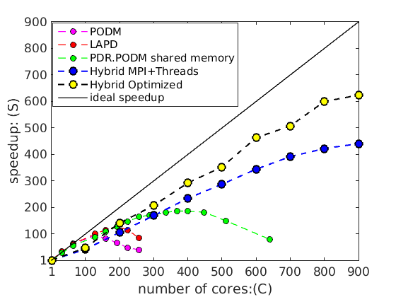
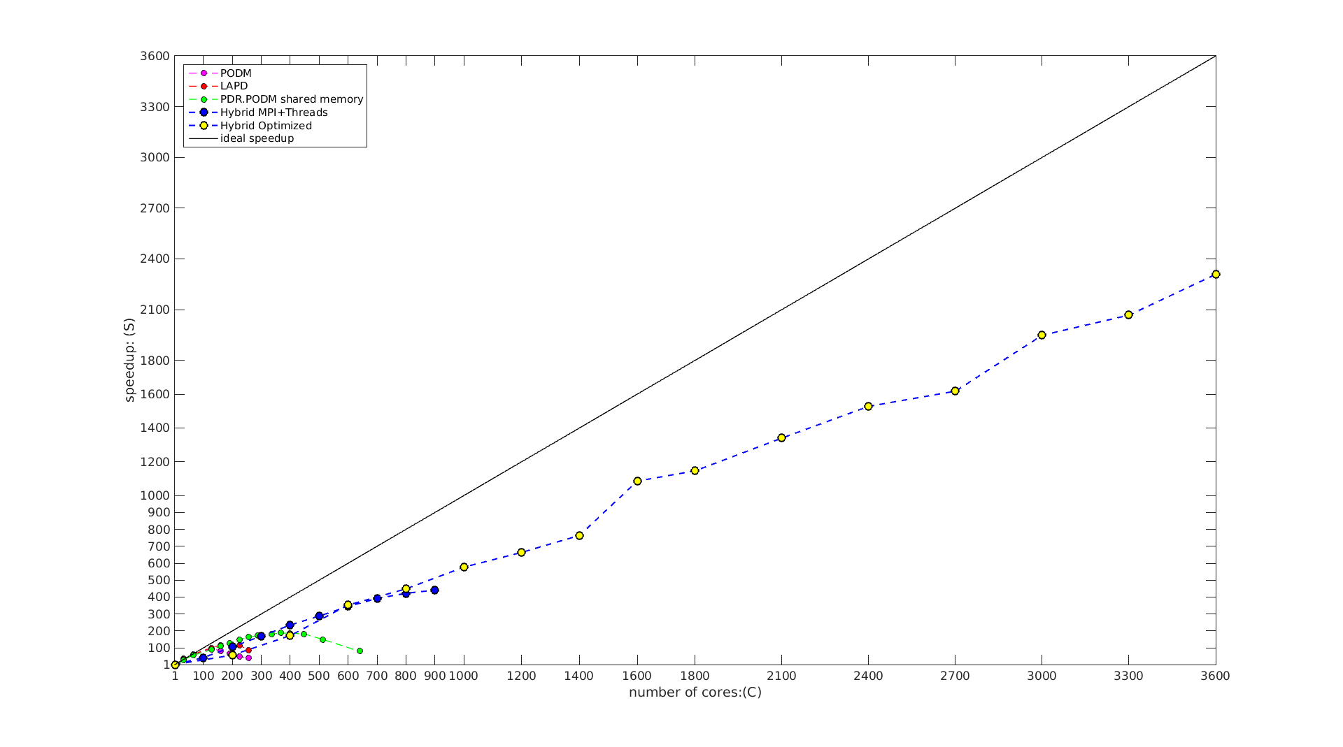
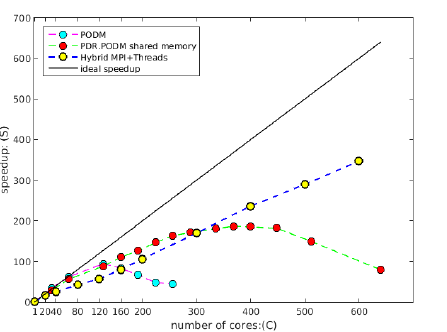
- the rack(s)-level (30 nodes with 20 cores each) using MPI+threads and CRTC’s I2M conversion software, the PDR.PODM’s scalable speedup is increasing linearly with a mesh 1.14 billion elements (using 600 cores). Figure 2 depicts the performance for both Distributed Shared Memory paradigm on cc-NUMA machines and Distributed Memory paradigm on a cluster of nodes at CRTC.
|
|
| Figure 1 : Comparison of dihedral angle distributions for PDR meshes generated using 1, 2, 4, 8, 16, and 32 cores. The mesh size is approximately 2 million. |
Figure 2 : Weak (scalable) speedup of PODM and PDR.PODM cc-NUMA using DSM and PDR.PODM on Distributed Memory using MPI + Threads |
Highlights of Findings
CRTC team managed to generate with PDR guaranteed quality 104 billion element mesh using 256 nodes with 64 cores each (i.e., 16,384 cores total) in 1029 seconds. This is the largest mesh size generated so far to the best of our knowledge and suggests:
- very good end-user productivity and
- a solid path to effectively utilize about 20,000,000 cores by 2030 by doubling the number of cores used (effectively) every year for the next 10 years.
CRTC team identified a new issue (and subsequent requirement): reproducibility. Use of TetGen in distributed memory implementation of the PDR exposed an underlying issue (strong and weak reproducibility) that is not apparent in shared memory implementations. The reproducibility issue (for precise definition see the full report) depends on the underlying sequential mesh generation code to maximize code re-use. In this specific case TetGen was used. When using TetGen over PDR’s distributed memory implementation (i.e., using MPI) a mesh needs to be reconstructed out of a set of points and tetrahedra, in order to populate the data structures of TetGen and to continue refining the leaf from where it was left before. Although this capability exists as a function in TetGen (tetgenmesh::reconstruct()) the reconstruction procedure is not robust enough even for simple inputs. AFLR is tested at ODU and it passes the weak reproducibility requirement. The same is true for both PODM and CTD3D developed at ODU.
Parallel Data Refinement (PDR)
CDT3D
While the scalability studies are progressing, ODU invested on the development of parallel (speculative i.e., lower level of the telescopic approach) advancing front with local reconnection method similar to methods implemented in AFLR. CTD3D is an alternative to AFLR and TetGen. However, in contrast to those codes, its strength is its scalability -- functionality will be added as it is need it. CTD3D code is developed from scratch to: (i) improve boundary recovery for complex geometries (for example AFLR can not recover the faces in DLRF6-Airbus), meet all parallel mesh generation requirements including reproducibility, be highly robust code (for example AFLR can not terminate on the 50K complexity ONERA adaptive case available here ) and most important easily integrated within the telescopic approach. Preliminary results on the performance and comparison with AFLR presented in the table bellow and full report will by published this summer (2018) in AIAA Aviation proceedings [2]. This suggests that fairly quickly we will be able to replace the scalability results presented earlier but this time for complex geometries pertinent to NASA's interests (see nacelle engine, rocket and launch vehicle and Onera M6 ).
| Case | Software | #Cores | %Slivers (w/o improv.) (x10-3) |
#Tets (w/ improv.) (M) |
Min/Max Angle (w/ improv.) (deg) |
Initial Grid (sec) |
Refinement (min) |
Improvement (min) |
Total (min) | |||||||||
|---|---|---|---|---|---|---|---|---|---|---|---|---|---|---|---|---|---|---|
| Nacelle | CDT3D | 1 | 3.74 | 43.65 | 13.57°/153.44° | 1.36 | 20.01 | 14.30 | 34.33 | |||||||||
| CDT3D | 12 | 3.70 | 42.85 | 12.06°/159.52° | 1.36 | 5.02 | 18.59 | 23.64 | ||||||||||
| AFLR | 1 | 2.97 | 43.16 | 7.00°/164.86° | 5.63 | 22.59 | 6.40 | 29.09 | ||||||||||
| Rocket | CDT3D | 1 | 2.96 | 118.41 | 9.39°/159.30° | 1.58 | 52.85 | 64.56 | 117.44 | |||||||||
| CDT3D | 12 | 2.95 | 119.06 | 9.21°/158.33° | 1.58 | 14.51 | 68.23 | 82.76 | ||||||||||
| AFLR | 1 | 3.05 | 123.13 | 5.58°/164.75° | 6.76 | 131.89 | 25.41 | 157.42 | ||||||||||
| Lv2b | CDT3D | 1 | 5.09 | 98.21 | 6.60°/159.68° | 5.45 | 41.57 | 94.63 | 136.29 | |||||||||
| CDT3D | 12 | 4.69 | 113.99 | 8.24°/158.59° | 5.45 | 12.92 | 62.36 | 75.37 | ||||||||||
| AFLR | 1 | 3.49 | 104.10 | 6.84°/164.88° | 16.97 | 98.24 | 18.51 | 117.03 | ||||||||||
Integration of Loosely Coupled Approach with Tightly Coupled using CDT3D and the Parallel Runtime System (PREMA)
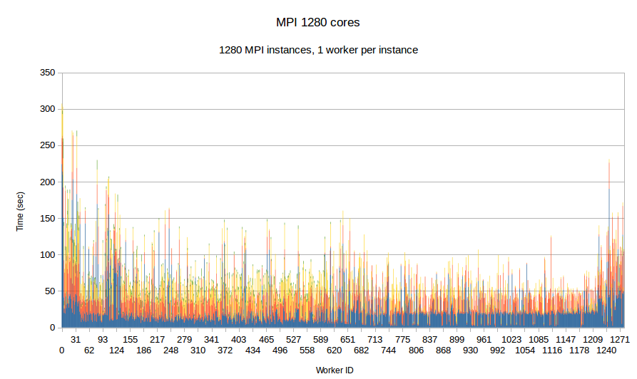
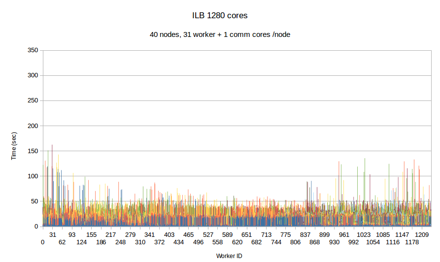
Earlier integration of PDR and Optimistic Parallel approach suggest promising results, despite the fact that the issue of balancing the work-load was not fully addressed i.e., it was addressed only at the inter-node level i.e., only between cores in the same node. In this task, a loosely coupled approach is integrated with a tightly coupled approach and in addition the workload balance is fully addressed transparently by the runtime system at the node level and the Optimistic code at the core level for each individual node. The Figure bellow depicts the comparison between ....
|
|
| Figure Per worker load comparison between MPI and PREMA with ILB on 1280 cores. MPI uses 1280 cores as workers while PREMA uses 1240 cores as workers plus 40 cores for servicing communication requests. Initial mesh: 30M elements and 4,500 subdomains | |
Integration of error-based anisotropic adaptive (CTD3D) grids with MIT's CFD solver
-
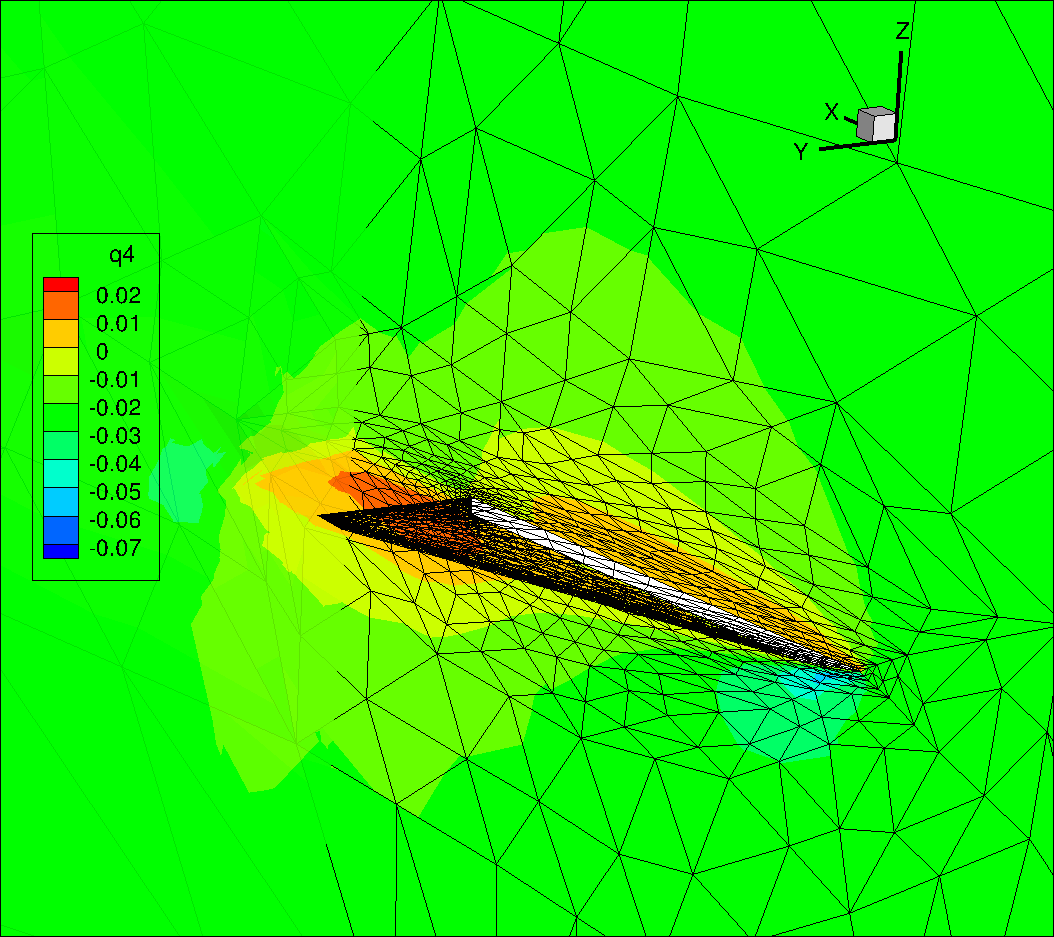
integration of anisotropic adaptive ACDT3D is completed for a simple 3D geometry (see figure ) with MIT's CFD solvers using the following boundary/farfield conditions: Mach 0.3, Reynolds 4000, Prandtl 0.72, AoA 12.5 degree.
The Farfield boundary was a Characteristic Full state boundary condition, this means the prescribed far field state was used with the interior state to impose a flux boundary condition appropriate to the flow of the characteristics. The surface of the wing was an adiabatic no slip wall, and the symmetry plane was a symmetry boundary condition. The outflow was a subsonic pressure outflow.
Given that the point of the exercise was the integration of ACTD3D with the CFD solver at MIT, a small mesh-size problem was used. Namely, the target number of degrees of freedom was 10000, and the polynomial order of the solution was p = 2. The viscous stabilization used was Bassi-Rebay's second version, commonly referred to as BR2.
In summary, the above deliverables on PDR, CTD3D on adaptive anisotropic grid generation, integration of CTD3D with PREMA and its integration with MIT's efforts on error-metric address all tasks from 1-5.
Moving Forward to Extreme Scales: Performance Data from up to 16k cores
| No. of cores | 4096 (64*64) | 8192 (128*64) | 16384 (256*64) | |||
|---|---|---|---|---|---|---|
| No. of elements | 24.8 billion | 49.7 billion | 101.4billion | |||
| Depth | Depth 4 | Depth 5 | Depth 4 | Depth 5 | Depth 4 | Depth 5 |
| Int to pointer time | 9.7 | 79.0 | 9.7 | 80.1 | 9.7 | 79.4 |
| Pointer to int time | 5.2 | 44.8 | 5.2 | 41.5 | 5.2 | 41.4 |
| Move data time | 37.2 | 236.3 | 33.2 | 269.1 | 34.6 | 296.8 |
| Meshing Time | 187.5 | 285.0 | 208.1 | 259.7 | 243.8 | 243.4 |
| Polling time | 162.6 | 288.9 | 96.8 | 259.9 | 66.5 | 258.6 |
| Waiting (idle) time | 350.0 | 9.2 | 1018.6 | 35.9 | 2108.6 | 98.0 |
| Total | 752.1 | 943.3 | 1371.6 | 966.2 | 2468.5 | 1017.6 |
