Internal:Annual Reports: Difference between revisions
| (40 intermediate revisions by 2 users not shown) | |||
| Line 1: | Line 1: | ||
= JLAB - CNF Project = | |||
== Time Schedule == | |||
* 2D | |||
** plain vanilla adaptivity | |||
***mesh files (done) | |||
*** docker image ( due Nov 20) + user guide | |||
*** document (due Jan 15) | |||
** More advanced features (ex query mesh (for interpolation)) (due 2020 proposal, Nov 15) | |||
* 3D | |||
** isostropic (done) | |||
** adaptive | |||
** plain vanilla | |||
***mesh files (done) | |||
*** docker (due Nov 25) | |||
*** document (due Jan 15) | |||
** advanced adaptivity | |||
*** explore ways for different metrics (fixed set of sizing functions)(die 2020 proposal; Nov 15) | |||
*** expose sizing function API (due 2021 proposal) | |||
* 4D | |||
** sequential (due 2020; nov 15) | |||
***plain vanilla adaptivity (due 2020l nov 15) | |||
*** docker , document, query etc (due to 2020; nov 15) | |||
**parallel (due to 2021) | |||
== Deliverables == | |||
Short-term deliverables (6 months): | |||
a Post-processing of the output of the PARTONS GPD physics model for generation of NRRD/DICOM images and their segmentation (by July 1); | |||
:* Gagik NRRD format conversion | |||
:* Angelos segmentation (refer to figure) | |||
:* Christos interpolation (refer to figure) | |||
b Generation of n-dimensional sequence of tessellations for numerical integration (by July 1); -- the "sequence" part will be completed by Dec. 31. Report on Jan. 15, 2020. | |||
:* Phase 1 , isotropic case (Nikos & Christos & Angelos) ( what we delivered on June 2019) | |||
:* Phase 2, adaptive isotropic case (Spiros & Christos) | |||
c Use of n-dimensional tessellations for efficient sampling of physics model and generation of event distributions for physics analysis; | |||
:* Motivation (Christian) | |||
:* Preliminary Results - Monte-Carlo etc. (Gagik) | |||
d Experiment with 3D Slicer and Paraview open source imaging and visualization systems to display visual representations of the entire space and/or m-slices, with m < n (by Sept. 30); | |||
:* Add figures from BOX, box slicer & paraview, (Nikos - Slicer Imaging Workshop / Data format & Christos) | |||
e Topical workshop including experts in imaging, exascale computing, uncertainty quantification, and nuclear physics to guide further developments (by Sept. 30). | |||
:* Nikos | |||
:* Data Format (HDF) | |||
f Future Work | |||
:* Machine Learning Short version of wiki and preliminary results (Polykarpos) | |||
:* Python plugins (Joi, Kevin, Angelos,Christos) | |||
:* 4D (Nikos) | |||
1. Christos/Angelos: 3D isotropic PODM & docker: | |||
2. Polykarpos/Angelos: ML CNF (define the problem, progress so far) | |||
3. Christos/Spiros: 2D/3D adaptivity using CNF input or other user defined means. | |||
[https://drive.google.com/file/d/1XCU72D2Abt40ZdwLbqtN62NZF6plxKc-/view?usp=sharing Final Report @ Google Docs] | |||
[https://odu.box.com/s/18xlq590rs4zvs2kh7c05apy0ej8h68w Final Report (offline) ] | |||
= NASA Project = | |||
== Summary == | == Summary == | ||
''' | === Year 1: === | ||
'''Full Report : ''' [http://cs.odu.edu/crtc/PDR/cepm_internal/NRA_Interim_Report_Year1_Final.pdf http://cs.odu.edu/crtc/PDR/cepm_internal/NRA_Interim_Report_Year1_Final.pdf] | |||
The first year of this project aimed at investigating a tangible implementation plan for design a multi-layered algorithmic and software framework for 3D tetrahedral anisotropic parallel mesh generation and adaptation relying on error-based metrics. | The first year of this project aimed at investigating a tangible implementation plan for design a multi-layered algorithmic and software framework for 3D tetrahedral anisotropic parallel mesh generation and adaptation relying on error-based metrics. | ||
The main accomplishments have been: | The main accomplishments have been: | ||
<ol> | |||
<li>Identified (and in two cases started) the implementation of three mesh generation approaches for the lower chip-level (optimistic) implementation of 3D tetrahedral anisotropic parallel mesh generation and adaptation: | |||
<ol style="list-style-type:lower-roman"> | |||
<li> the default method/software based on sequential AFLR3 from MSU –identified basic operations and challenges, </li> | |||
<li> a new implementation (CDT3D) using known algorithms for anisotropic mesh generation and adaptation, but taking into account lessons learned from and new requirements for ODU’s telescopic approach and </li> | |||
<li> a completely new method in which an anisotropic 3D metric is embedded and isotropically meshed on a manifold in 4D dimensional space which could leverage ODU’s 4D Delaunay-based parallel optimistic I2M conversion technology. </li> | |||
</ol> | |||
</li> | |||
<li> Started the process of designing and implementing two out of four layers of the telescopic approach using TetGen (Delaunay-based open source mesh generation software): </li> | |||
<ol style="list-style-type:lower-roman"> | |||
<li> Parallel Constrained (PC) layer that targets multiple racks of nodes, </li> | |||
<li> Parallel Data Refinement (PDR) layer that targets multiple nodes (within a single rack). </li> | |||
</ol> | |||
<li> Identified test cases with NASA/LaRC (CAD model of a half DLR-F6 Airbus-type aircraft and a series of complex components from AIM@SHAPE repository) to evaluate mesh generation and adaptation modules. </li> | |||
<li> Identified two state-of-the-art software runtime systems from industry, academia and national labs that meet the requirements of the proposed Multi-Layered Runtime System (MRTS): | |||
<ol style="list-style-type:lower-roman"> | |||
<li> OCR is a runtime system from Intel and </li> | |||
<li> Argo is an exascale-era ecosystem build by a collaboration effort between DoE labs (mainly ANL) and academia. </li> | |||
</ol> | |||
</li> | |||
</ol> | |||
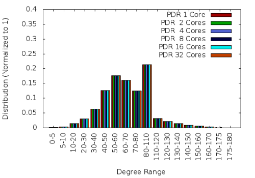
The results so far are promising. For example, the initial PDR implementation using TetGen and homegrown I2M conversion methods is stable (i.e., generate the same quality mesh with the sequential code, see Figure 1), robust (i.e., can mesh all the geometries tried –those the sequential code manages to process), with more than 95% code re-use and it is efficient both at: | |||
# the node-level (with 32 cores): the fixed speedup is more than 16 for a mesh with 800M element and scalable (weak) speedup is close to 20. | |||
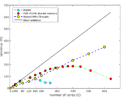
# the rack(s)-level (30 nodes with 20 cores each) using MPI+threads and CRTC’s I2M conversion software, the PDR.PODM’s scalable speedup is increasing linearly with a mesh 1.14 billion elements (using 600 cores). Figure 2 depicts the performance for both Distributed Shared Memory paradigm on cc-NUMA machines and Distributed Memory paradigm on a cluster of nodes at CRTC. We anticipate better performance for AFLR3 and PDR-like approach we plan to start implementing in Years 2 and 3 of this project. | |||
{| | |||
|- | |||
|[[File:Pdr_quality.png|500px|link=]] | |||
|[[File:Podm_dsm_mpi.png|500px|link=]] | |||
|- | |||
|'''Figure 1 :''' Comparison of dihedral angle distributions for PDR meshes<br> generated using 1, 2, 4, 8, 16, and 32 cores. The mesh size is approximately 2 million. | |||
|'''Figure 2 :''' Weak (scalable) speedup of PODM and PDR.PODM cc-NUMA using DSM and PDR.PODM on Distributed Memory using MPI + Threads | |||
|} | |||
=== Year 2: === | |||
'''Full Report : ''' [http://cs.odu.edu/crtc/PDR/cepm_internal/NRA_Annual_Report_Year2_Final.pdf http://cs.odu.edu/crtc/PDR/cepm_internal/NRA_Annual_Report_Year2_Final.pdf] | |||
The second year aimed at an implementation for Parallel Data Refinement (PDR) layer of the Telescopic approach for: | |||
<ol> | |||
<li> 3D tetrahedral parallel mesh generation and adaptation </li> | |||
<li> using on error-based metrics. Specifically: | |||
<ol style="list-style-type:lower-roman"> | |||
<li> Implementation of the PDR.AFLR and PDR.MOESS layers on shared memory machines i.e., at the node-level. </li> | |||
<li>Revisit the design of the HPC runtime system and the telescopic approach for parallel mesh generation using NASA’s feedback and error-based metric requirements from CFD solvers. </li> | |||
<li> Continue the evaluation of current and emerging relevant communication substrates and incorporate NASA’s feedback in the first HPC runtime system design in order to finalize it. </li> | |||
</ol> | |||
</li> | |||
</ol> | |||
==== Summary of Accomplishments ==== | |||
The major highlight of Year 2 is that the ODU team managed to generate with PDR guaranteed quality 104 billion element mesh using 256 nodes with 64 cores each (i.e., 16,384 cores total) in 1029 seconds. This is the largest mesh size generated so far to the best of our knowledge and suggests: | |||
#very good end-user productivity and | |||
#a solid path to effectively utilize about 20,000,000 cores by 2030 by doubling the number of cores used (effectively) every year for the next 12 years. | |||
During the second year of the project the main accomplishments pertinent to expected outcomes have been: | |||
<ol> | |||
<li>ODU finalized the design of the runtime system and implemented the first prototype | |||
–outside the scope of this project—but yet quite useful exercise for our future plans. | |||
A journal paper is completed and is prepared for publication. | |||
A short version is submitted to AIAA Aviation’18 and it is appended in this report. | |||
</li> | |||
<li> | |||
ODU completed the PDR implementation on shared memory (at the node level) and tested it using TetGen | |||
(an open source software from Germany), since due to high software complexity of AFLR’s modifications MSU | |||
could not complete them on time. | |||
<ol style="list-style-type:lower-roman"> | |||
<li> | |||
Instead, the ODU team decided to look into AFLR modifications (with some help from MSU) and there is a good progress in modifying AFLR to meet PDR’s API. This year we completed the sequential validation of the AFLR modifications. | |||
</li> | |||
<li> | |||
Also, MSU completed sequential anisotropic adaptivity instead of PDR.AFLR. This change will benefit this project in the near future i.e., next phase of the project. | |||
</li> | |||
</ol> | |||
</li> | |||
<li> MIT, Implemented a version of MOESS that is parallel except for the solution of the metric optimization problem, | |||
which remains in serial. Current work is exploring use of PETSC’s parallel optimization methods to solve this | |||
optimization problem. All other aspects of the MOESS implementation are in parallel (including error estimation | |||
and local solves). As well, the MOESS algorithm has been used with various metric-based meshers including AFLR, NASA Langley’s REFINE, Boeing’s EPIC, and INRIA Feflo.a methods. | |||
</li> | |||
<li> | |||
ODU, completed the evaluation of current and emerging relevant communication substrates and | |||
incorporate NASA’s feedback and decided to invest at Argo from ANL/DoE as the future communication substrate. | |||
</li> | |||
<li> | |||
MIT, developed an embedding approach for general N-dimensional metric based meshing, specifically targeting application to 4D (i.e. 3D space + time) adaptive meshing. This approach was presented at the 2017 International Meshing Roundtable winning student best paper. | |||
</li> | |||
</ol> | |||
<div><ul> | |||
<li style="display: inline-block;"> | |||
[[File:With_optimized_900.png|thumb|none|500px|Figure 1 : caption ]] | |||
</li> | |||
</ul> | |||
</div> | |||
=== Year 3 (Interim Report): === | |||
==== PDR ==== | |||
<div><ul> | |||
<li style="display: inline-block;"> [[File:With_optimized_1800.png|thumb|none|500px| Figure 1 : caption ]] </li> | |||
<li style="display: inline-block;"> [[File:With_optimized_3600.png|thumb|none|500px| Figure 2 : caption ]] </li> | |||
</ul></div> | |||
==== CDT3D ==== | |||
{| class="wikitable" style="text-align:center;" | |||
|+ Evaluation results on unstructured grid generation. CDT3D is compared with state-of-the-art technology AFLR v16.9.19. CDT3D’s runs are performed with 1 and 12 hardware cores. AFLR is a sequential code. This table lists the parameters of the evaluation. The sliver elements have a dihedral angle smaller than 2° or larger than 178°. The initial grid includes Delaunay tetrahedralization and Boundary Recovery. The I/O time is not included. The experiments were performed on a Dell workstation with Linux Ubuntu 12.10, using a 12-core Intel Xeon CPU X5690@3.47 GHz, and 96 GB RAM. | |||
|- | |||
! scope="col" | Case !! colspan=2 | Software !! colspan=2 | #Cores !! colspan=2 | %Slivers<br>(w/o improv.)<br>(x10<sup>-3</sup>) !! colspan=2 | #Tets<br>(w/ improv.)<br>(M) !! colspan=2 | Min/Max Angle<br>(w/ improv.)<br>(deg) !! colspan=2 | Initial Grid<br>(sec) !! colspan=2 | Refinement<br>(min) !! colspan=2 | Improvement<br>(min) !! colspan=2 | Total<br>(min) | |||
|- | |||
! rowspan=3 | Nacelle | |||
| colspan=2 | CDT3D || colspan=2 | 1 || colspan=2 | 3.74 || colspan=2 | 43.65 || colspan=2 | 13.57°/153.44° || colspan=2 | 1.36 || colspan=2 | 20.01 || colspan=2 | 14.30 || colspan=2 | 34.33 | |||
|- | |||
| colspan=2 | CDT3D || colspan=2 | 12 || colspan=2 | 3.70 || colspan=2 | 42.85 || colspan=2 | 12.06°/159.52° || colspan=2 | 1.36 || colspan=2 | 5.02 || colspan=2 | 18.59 || colspan=2 | 23.64 | |||
|- | |||
| colspan=2 | AFLR || colspan=2 | 1 || colspan=2 | 2.97 || colspan=2 | 43.16 || colspan=2 | 7.00°/164.86° || colspan=2 | 5.63 || colspan=2 | 22.59 || colspan=2 | 6.40 || colspan=2 | 29.09 | |||
|- | |||
! rowspan=3 | Rocket | |||
| colspan=2 | CDT3D || colspan=2 | 1 || colspan=2 | 2.96 || colspan=2 | 118.41 || colspan=2 | 9.39°/159.30° || colspan=2 | 1.58 || colspan=2 | 52.85 || colspan=2 | 64.56 || colspan=2 | 117.44 | |||
|- | |||
| colspan=2 | CDT3D || colspan=2 | 12 || colspan=2 | 2.95 || colspan=2 | 119.06 || colspan=2 | 9.21°/158.33° || colspan=2 | 1.58 || colspan=2 | 14.51 || colspan=2 | 68.23 || colspan=2 | 82.76 | |||
|- | |||
| colspan=2 | AFLR || colspan=2 | 1 || colspan=2 | 3.05 || colspan=2 | 123.13 || colspan=2 | 5.58°/164.75° || colspan=2 | 6.76 || colspan=2 | 131.89 || colspan=2 | 25.41 || colspan=2 | 157.42 | |||
|- | |||
! rowspan=3 | Lv2b | |||
| colspan=2 | CDT3D || colspan=2 | 1 || colspan=2 | 5.09 || colspan=2 | 98.21 || colspan=2 | 6.60°/159.68° || colspan=2 | 5.45 || colspan=2 | 41.57 || colspan=2 | 94.63 || colspan=2 | 136.29 | |||
|- | |||
| colspan=2 | CDT3D || colspan=2 | 12 || colspan=2 | 4.69 || colspan=2 | 113.99 || colspan=2 | 8.24°/158.59° || colspan=2 | 5.45 || colspan=2 | 12.92 || colspan=2 | 62.36 || colspan=2 | 75.37 | |||
|- | |||
| colspan=2 | AFLR || colspan=2 | 1 || colspan=2 | 3.49 || colspan=2 | 104.10 || colspan=2 | 6.84°/164.88° || colspan=2 | 16.97 || colspan=2 | 98.24 || colspan=2 | 18.51 || colspan=2 | 117.03 | |||
|} | |||
==== CDT3D + PREMA ==== | |||
{| | |||
|- | |||
|[[File:MPI_CDT3D_1280.png|600px|link=]] | |||
|[[File:PREMA_CDT3D_1280.png|600px|link=]] | |||
|- | |||
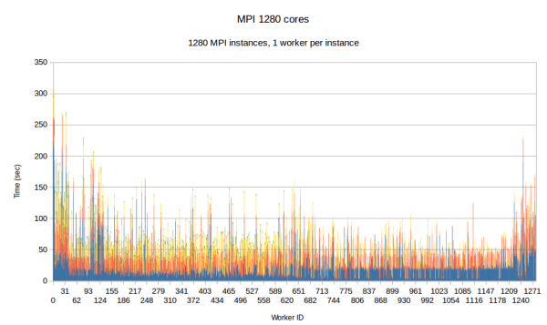
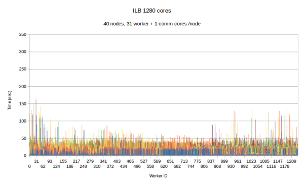
| colspan="2" | ''' Figure Per worker load comparison between MPI and PREMA with ILB on 1280 cores. MPI uses 1280 as workers while PREMA uses 1240 for workers plus 40 for communication. Initial mesh: 30mil elements, 4.5k subdomains''' | |||
|} | |||
==== CDT3D + MIT ==== | |||
<div><ul> | |||
<li style="display: inline-block;"> | |||
[[File:DeltaWing_P2_zmom_a15.png|thumb|none|500px| Figure 1 : caption ]] | |||
</li> | |||
</ul></div> | |||
Latest revision as of 12:35, 6 November 2019
JLAB - CNF Project
Time Schedule
- 2D
- plain vanilla adaptivity
- mesh files (done)
- docker image ( due Nov 20) + user guide
- document (due Jan 15)
- More advanced features (ex query mesh (for interpolation)) (due 2020 proposal, Nov 15)
- plain vanilla adaptivity
- 3D
- isostropic (done)
- adaptive
- plain vanilla
- mesh files (done)
- docker (due Nov 25)
- document (due Jan 15)
- advanced adaptivity
- explore ways for different metrics (fixed set of sizing functions)(die 2020 proposal; Nov 15)
- expose sizing function API (due 2021 proposal)
- 4D
- sequential (due 2020; nov 15)
- plain vanilla adaptivity (due 2020l nov 15)
- docker , document, query etc (due to 2020; nov 15)
- parallel (due to 2021)
- sequential (due 2020; nov 15)
Deliverables
Short-term deliverables (6 months):
a Post-processing of the output of the PARTONS GPD physics model for generation of NRRD/DICOM images and their segmentation (by July 1);
- Gagik NRRD format conversion
- Angelos segmentation (refer to figure)
- Christos interpolation (refer to figure)
b Generation of n-dimensional sequence of tessellations for numerical integration (by July 1); -- the "sequence" part will be completed by Dec. 31. Report on Jan. 15, 2020.
- Phase 1 , isotropic case (Nikos & Christos & Angelos) ( what we delivered on June 2019)
- Phase 2, adaptive isotropic case (Spiros & Christos)
c Use of n-dimensional tessellations for efficient sampling of physics model and generation of event distributions for physics analysis;
- Motivation (Christian)
- Preliminary Results - Monte-Carlo etc. (Gagik)
d Experiment with 3D Slicer and Paraview open source imaging and visualization systems to display visual representations of the entire space and/or m-slices, with m < n (by Sept. 30);
- Add figures from BOX, box slicer & paraview, (Nikos - Slicer Imaging Workshop / Data format & Christos)
e Topical workshop including experts in imaging, exascale computing, uncertainty quantification, and nuclear physics to guide further developments (by Sept. 30).
- Nikos
- Data Format (HDF)
f Future Work
- Machine Learning Short version of wiki and preliminary results (Polykarpos)
- Python plugins (Joi, Kevin, Angelos,Christos)
- 4D (Nikos)
1. Christos/Angelos: 3D isotropic PODM & docker:
2. Polykarpos/Angelos: ML CNF (define the problem, progress so far)
3. Christos/Spiros: 2D/3D adaptivity using CNF input or other user defined means.
Final Report @ Google Docs Final Report (offline)
NASA Project
Summary
Year 1:
Full Report : http://cs.odu.edu/crtc/PDR/cepm_internal/NRA_Interim_Report_Year1_Final.pdf
The first year of this project aimed at investigating a tangible implementation plan for design a multi-layered algorithmic and software framework for 3D tetrahedral anisotropic parallel mesh generation and adaptation relying on error-based metrics.
The main accomplishments have been:
- Identified (and in two cases started) the implementation of three mesh generation approaches for the lower chip-level (optimistic) implementation of 3D tetrahedral anisotropic parallel mesh generation and adaptation:
- the default method/software based on sequential AFLR3 from MSU –identified basic operations and challenges,
- a new implementation (CDT3D) using known algorithms for anisotropic mesh generation and adaptation, but taking into account lessons learned from and new requirements for ODU’s telescopic approach and
- a completely new method in which an anisotropic 3D metric is embedded and isotropically meshed on a manifold in 4D dimensional space which could leverage ODU’s 4D Delaunay-based parallel optimistic I2M conversion technology.
- Started the process of designing and implementing two out of four layers of the telescopic approach using TetGen (Delaunay-based open source mesh generation software):
- Parallel Constrained (PC) layer that targets multiple racks of nodes,
- Parallel Data Refinement (PDR) layer that targets multiple nodes (within a single rack).
- Identified test cases with NASA/LaRC (CAD model of a half DLR-F6 Airbus-type aircraft and a series of complex components from AIM@SHAPE repository) to evaluate mesh generation and adaptation modules.
- Identified two state-of-the-art software runtime systems from industry, academia and national labs that meet the requirements of the proposed Multi-Layered Runtime System (MRTS):
- OCR is a runtime system from Intel and
- Argo is an exascale-era ecosystem build by a collaboration effort between DoE labs (mainly ANL) and academia.
The results so far are promising. For example, the initial PDR implementation using TetGen and homegrown I2M conversion methods is stable (i.e., generate the same quality mesh with the sequential code, see Figure 1), robust (i.e., can mesh all the geometries tried –those the sequential code manages to process), with more than 95% code re-use and it is efficient both at:
- the node-level (with 32 cores): the fixed speedup is more than 16 for a mesh with 800M element and scalable (weak) speedup is close to 20.
- the rack(s)-level (30 nodes with 20 cores each) using MPI+threads and CRTC’s I2M conversion software, the PDR.PODM’s scalable speedup is increasing linearly with a mesh 1.14 billion elements (using 600 cores). Figure 2 depicts the performance for both Distributed Shared Memory paradigm on cc-NUMA machines and Distributed Memory paradigm on a cluster of nodes at CRTC. We anticipate better performance for AFLR3 and PDR-like approach we plan to start implementing in Years 2 and 3 of this project.
|
|
| Figure 1 : Comparison of dihedral angle distributions for PDR meshes generated using 1, 2, 4, 8, 16, and 32 cores. The mesh size is approximately 2 million. |
Figure 2 : Weak (scalable) speedup of PODM and PDR.PODM cc-NUMA using DSM and PDR.PODM on Distributed Memory using MPI + Threads |
Year 2:
Full Report : http://cs.odu.edu/crtc/PDR/cepm_internal/NRA_Annual_Report_Year2_Final.pdf
The second year aimed at an implementation for Parallel Data Refinement (PDR) layer of the Telescopic approach for:
- 3D tetrahedral parallel mesh generation and adaptation
- using on error-based metrics. Specifically:
- Implementation of the PDR.AFLR and PDR.MOESS layers on shared memory machines i.e., at the node-level.
- Revisit the design of the HPC runtime system and the telescopic approach for parallel mesh generation using NASA’s feedback and error-based metric requirements from CFD solvers.
- Continue the evaluation of current and emerging relevant communication substrates and incorporate NASA’s feedback in the first HPC runtime system design in order to finalize it.
Summary of Accomplishments
The major highlight of Year 2 is that the ODU team managed to generate with PDR guaranteed quality 104 billion element mesh using 256 nodes with 64 cores each (i.e., 16,384 cores total) in 1029 seconds. This is the largest mesh size generated so far to the best of our knowledge and suggests:
- very good end-user productivity and
- a solid path to effectively utilize about 20,000,000 cores by 2030 by doubling the number of cores used (effectively) every year for the next 12 years.
During the second year of the project the main accomplishments pertinent to expected outcomes have been:
- ODU finalized the design of the runtime system and implemented the first prototype –outside the scope of this project—but yet quite useful exercise for our future plans. A journal paper is completed and is prepared for publication. A short version is submitted to AIAA Aviation’18 and it is appended in this report.
-
ODU completed the PDR implementation on shared memory (at the node level) and tested it using TetGen
(an open source software from Germany), since due to high software complexity of AFLR’s modifications MSU
could not complete them on time.
- Instead, the ODU team decided to look into AFLR modifications (with some help from MSU) and there is a good progress in modifying AFLR to meet PDR’s API. This year we completed the sequential validation of the AFLR modifications.
- Also, MSU completed sequential anisotropic adaptivity instead of PDR.AFLR. This change will benefit this project in the near future i.e., next phase of the project.
- MIT, Implemented a version of MOESS that is parallel except for the solution of the metric optimization problem, which remains in serial. Current work is exploring use of PETSC’s parallel optimization methods to solve this optimization problem. All other aspects of the MOESS implementation are in parallel (including error estimation and local solves). As well, the MOESS algorithm has been used with various metric-based meshers including AFLR, NASA Langley’s REFINE, Boeing’s EPIC, and INRIA Feflo.a methods.
- ODU, completed the evaluation of current and emerging relevant communication substrates and incorporate NASA’s feedback and decided to invest at Argo from ANL/DoE as the future communication substrate.
- MIT, developed an embedding approach for general N-dimensional metric based meshing, specifically targeting application to 4D (i.e. 3D space + time) adaptive meshing. This approach was presented at the 2017 International Meshing Roundtable winning student best paper.
-
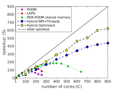
Figure 1 : caption

Year 3 (Interim Report):
PDR
-
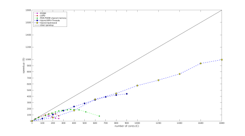
Figure 1 : caption -

Figure 2 : caption


CDT3D
| Case | Software | #Cores | %Slivers (w/o improv.) (x10-3) |
#Tets (w/ improv.) (M) |
Min/Max Angle (w/ improv.) (deg) |
Initial Grid (sec) |
Refinement (min) |
Improvement (min) |
Total (min) | |||||||||
|---|---|---|---|---|---|---|---|---|---|---|---|---|---|---|---|---|---|---|
| Nacelle | CDT3D | 1 | 3.74 | 43.65 | 13.57°/153.44° | 1.36 | 20.01 | 14.30 | 34.33 | |||||||||
| CDT3D | 12 | 3.70 | 42.85 | 12.06°/159.52° | 1.36 | 5.02 | 18.59 | 23.64 | ||||||||||
| AFLR | 1 | 2.97 | 43.16 | 7.00°/164.86° | 5.63 | 22.59 | 6.40 | 29.09 | ||||||||||
| Rocket | CDT3D | 1 | 2.96 | 118.41 | 9.39°/159.30° | 1.58 | 52.85 | 64.56 | 117.44 | |||||||||
| CDT3D | 12 | 2.95 | 119.06 | 9.21°/158.33° | 1.58 | 14.51 | 68.23 | 82.76 | ||||||||||
| AFLR | 1 | 3.05 | 123.13 | 5.58°/164.75° | 6.76 | 131.89 | 25.41 | 157.42 | ||||||||||
| Lv2b | CDT3D | 1 | 5.09 | 98.21 | 6.60°/159.68° | 5.45 | 41.57 | 94.63 | 136.29 | |||||||||
| CDT3D | 12 | 4.69 | 113.99 | 8.24°/158.59° | 5.45 | 12.92 | 62.36 | 75.37 | ||||||||||
| AFLR | 1 | 3.49 | 104.10 | 6.84°/164.88° | 16.97 | 98.24 | 18.51 | 117.03 | ||||||||||
CDT3D + PREMA
|
|
| Figure Per worker load comparison between MPI and PREMA with ILB on 1280 cores. MPI uses 1280 as workers while PREMA uses 1240 for workers plus 40 for communication. Initial mesh: 30mil elements, 4.5k subdomains | |
CDT3D + MIT
-
Figure 1 : caption
