Difference between revisions of "PDR.AFLR"
(→Stability) |
(→Stability) |
||
| Line 18: | Line 18: | ||
<li style="display: inline-block;"> [[File: nacelle_stability_1.png|thumb|none|650px|'''(c)''']] </li> | <li style="display: inline-block;"> [[File: nacelle_stability_1.png|thumb|none|650px|'''(c)''']] </li> | ||
</ul></div> | </ul></div> | ||
| − | The Fan and Turbine Disk surfaces were removed from the nacelle engine geometry. (a) and (b) show different viewpoints of the geometry. (c) compares the dihedral angle distributions of the output meshes between serial AFLR and PDR.AFLR. | + | :The Fan and Turbine Disk surfaces were removed from the nacelle engine geometry. (a) and (b) show different viewpoints of the geometry. (c) compares the dihedral angle distributions of the output meshes between serial AFLR and PDR.AFLR. |
<br><br><br><br> | <br><br><br><br> | ||
| Line 26: | Line 26: | ||
<li style="display: inline-block;"> [[File: missile_stability_1.png|thumb|none|600px|'''(c)''']] </li> | <li style="display: inline-block;"> [[File: missile_stability_1.png|thumb|none|600px|'''(c)''']] </li> | ||
</ul></div> | </ul></div> | ||
| − | The Plume and NearField embedded surfaces were removed from the missile1 geometry. (a) and (b) show different viewpoints of the geometry. (c) compares the dihedral angle distributions of the output meshes between serial AFLR and PDR.AFLR. | + | :The Plume and NearField embedded surfaces were removed from the missile1 geometry. (a) and (b) show different viewpoints of the geometry. (c) compares the dihedral angle distributions of the output meshes between serial AFLR and PDR.AFLR. |
<br><br><br><br> | <br><br><br><br> | ||
| Line 33: | Line 33: | ||
<li style="display: inline-block;"> [[File: missile2_stability_1.png|thumb|none|450px|'''(b)''']] </li> | <li style="display: inline-block;"> [[File: missile2_stability_1.png|thumb|none|450px|'''(b)''']] </li> | ||
</ul></div> | </ul></div> | ||
| − | The Plume and NearField embedded surfaces were removed from the missile2 geometry.(a) shows the modified missile2 geometry. (b) shows the dihedral angle distributions of the output meshes compared between the serial AFLR code and PDR.AFLR. | + | :The Plume and NearField embedded surfaces were removed from the missile2 geometry.(a) shows the modified missile2 geometry. (b) shows the dihedral angle distributions of the output meshes compared between the serial AFLR code and PDR.AFLR. |
<br><br><br><br> | <br><br><br><br> | ||
| Line 40: | Line 40: | ||
<li style="display: inline-block;"> [[File: defroster_stability_1.png|thumb|none|500px|'''(b)''']] </li> | <li style="display: inline-block;"> [[File: defroster_stability_1.png|thumb|none|500px|'''(b)''']] </li> | ||
</ul></div> | </ul></div> | ||
| − | (a) shows the defroster geometry. (b) shows the dihedral angle distributions of the output meshes compared between the serial AFLR code and PDR.AFLR. | + | :(a) shows the defroster geometry. (b) shows the dihedral angle distributions of the output meshes compared between the serial AFLR code and PDR.AFLR. |
<br><br><br><br> | <br><br><br><br> | ||
| Line 47: | Line 47: | ||
<li style="display: inline-block;"> [[File: rocket_stability_1.png|thumb|none|500px|'''(b)''']] </li> | <li style="display: inline-block;"> [[File: rocket_stability_1.png|thumb|none|500px|'''(b)''']] </li> | ||
</ul></div> | </ul></div> | ||
| − | (a) shows the rocket geometry. (b) shows the dihedral angle distributions of the output meshes compared between the serial AFLR code and PDR.AFLR. | + | :(a) shows the rocket geometry. (b) shows the dihedral angle distributions of the output meshes compared between the serial AFLR code and PDR.AFLR. |
<br><br><br><br> | <br><br><br><br> | ||
| Line 54: | Line 54: | ||
<li style="display: inline-block;"> [[File: dome_stability_1.png|thumb|none|450px|'''(b)''']] </li> | <li style="display: inline-block;"> [[File: dome_stability_1.png|thumb|none|450px|'''(b)''']] </li> | ||
</ul></div> | </ul></div> | ||
| − | (a) shows the dome geometry. (b) shows the dihedral angle distributions of the output meshes compared between the serial AFLR code and PDR.AFLR. | + | :(a) shows the dome geometry. (b) shows the dihedral angle distributions of the output meshes compared between the serial AFLR code and PDR.AFLR. |
<br><br><br><br> | <br><br><br><br> | ||
| Line 61: | Line 61: | ||
<li style="display: inline-block;"> [[File: nozzle_stability_1.png|thumb|none|450px|'''(b)''']] </li> | <li style="display: inline-block;"> [[File: nozzle_stability_1.png|thumb|none|450px|'''(b)''']] </li> | ||
</ul></div> | </ul></div> | ||
| − | (a) shows the nozzle geometry. (b) shows the dihedral angle distributions of the output meshes compared between the serial AFLR code and PDR.AFLR. | + | :(a) shows the nozzle geometry. (b) shows the dihedral angle distributions of the output meshes compared between the serial AFLR code and PDR.AFLR. |
<br><br><br><br> | <br><br><br><br> | ||
| Line 68: | Line 68: | ||
<li style="display: inline-block;"> [[File: curved_duct_stability_1.png|thumb|none|450px|'''(b)''']] </li> | <li style="display: inline-block;"> [[File: curved_duct_stability_1.png|thumb|none|450px|'''(b)''']] </li> | ||
</ul></div> | </ul></div> | ||
| − | (a) shows the curved duct geometry. (b) shows the dihedral angle distributions of the output meshes compared between the serial AFLR code and PDR.AFLR. | + | :(a) shows the curved duct geometry. (b) shows the dihedral angle distributions of the output meshes compared between the serial AFLR code and PDR.AFLR. |
<br><br><br><br> | <br><br><br><br> | ||
| Line 75: | Line 75: | ||
<li style="display: inline-block;"> [[File: radial_nozzle_stability_1.png|thumb|none|450px|'''(b)''']] </li> | <li style="display: inline-block;"> [[File: radial_nozzle_stability_1.png|thumb|none|450px|'''(b)''']] </li> | ||
</ul></div> | </ul></div> | ||
| − | (a) shows the radial nozzle geometry. (b) shows the dihedral angle distributions of the output meshes compared between the serial AFLR code and PDR.AFLR. | + | :(a) shows the radial nozzle geometry. (b) shows the dihedral angle distributions of the output meshes compared between the serial AFLR code and PDR.AFLR. |
<br><br><br><br> | <br><br><br><br> | ||
| Line 82: | Line 82: | ||
<li style="display: inline-block;"> [[File: horn_bulb_stability_1.png|thumb|none|450px|'''(b)''']] </li> | <li style="display: inline-block;"> [[File: horn_bulb_stability_1.png|thumb|none|450px|'''(b)''']] </li> | ||
</ul></div> | </ul></div> | ||
| − | (a) shows the horn bulb geometry. (b) shows the dihedral angle distributions of the output meshes compared between the serial AFLR code and PDR.AFLR. | + | :(a) shows the horn bulb geometry. (b) shows the dihedral angle distributions of the output meshes compared between the serial AFLR code and PDR.AFLR. |
<br><br><br><br> | <br><br><br><br> | ||
= Scalability = | = Scalability = | ||
The parallelization of AFLR is currently a work-in-progress. During runtime, the PDR.AFLR method will expose data decomposition information (number of subdomains waiting to be refined) to our underlying run-time system, PREMA 2.0. In turn, PREMA 2.0 will facilitate work-load balancing and guide the program’s execution towards the most efficient utilization of hardware resources. PREMA 2.0 is a parallel runtime system that supports one-sided communication, global address space and load balancing for adaptive and irregular applications. This runtime system serves as an underlying layer that alleviates the burden of monitoring data and computations in parallel, an ideal candidate to support the execution of PDR.AFLR. | The parallelization of AFLR is currently a work-in-progress. During runtime, the PDR.AFLR method will expose data decomposition information (number of subdomains waiting to be refined) to our underlying run-time system, PREMA 2.0. In turn, PREMA 2.0 will facilitate work-load balancing and guide the program’s execution towards the most efficient utilization of hardware resources. PREMA 2.0 is a parallel runtime system that supports one-sided communication, global address space and load balancing for adaptive and irregular applications. This runtime system serves as an underlying layer that alleviates the burden of monitoring data and computations in parallel, an ideal candidate to support the execution of PDR.AFLR. | ||
Latest revision as of 12:51, 29 March 2018
Introduction
For the last 30 years, legacy Finite Element (FE) mesh generation methods and software were typically developed with a focus on high performance for single core architectures and without any thought towards scalability for a large number of cores. These codes are still used for production in several industries, including NASA. However, NASA’s Computational Fluid Dynamics (CFD) 2030 Vision will require those highly functional codes to run on large-scale parallel architectures. Highly optimized sequential versions of existing state-of-the-art mesh generation codes, in addition to geometric and numerical challenges imposed by the nature of mesh generation complexity, makes their parallelization a highly challenging problem. In this project, we focus on one of the top, industrial strength mesh generators, called Advancing Front Local Reconnection (AFLR), which is used by NASA, the DoD, and DoE, as well as a number of aerospace industry top research groups. AFLR has not been fully parallelized to properly utilize large-scale supercomputing hardware.
Overview
Modifications were made to AFLR to enable its execution within the Parallel Data Refinement (PDR, a generalized version of Parallel Delaunay Refinement meant to be capable of utilizing any mesh generator, i.e. code re-use) method and software framework (specifically the non-progressive approach) while maintaining AFLR’s full functionality and providing stability i.e., ensuring that the quality of the mesh generated (from each of the individually refined subdomains) is comparable to that of a mesh generated sequentially (by serial AFLR). The quality is defined in terms of the shape and number of the elements. PDR decomposes a meshing problem by using an octree consisting of numerous leaves, or subdomains, that each hold a part of the mesh. The general idea of PDR is to concurrently refine the octree leaves while maintaining mesh conformity. This methodology is proven to generate a conforming mesh after refining the subdomains generated from an input geometry using data decomposition.
Reproducibility
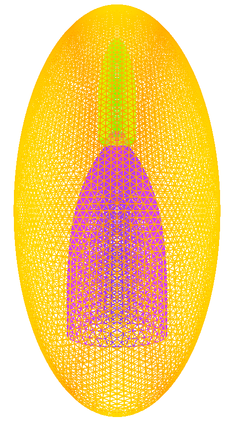
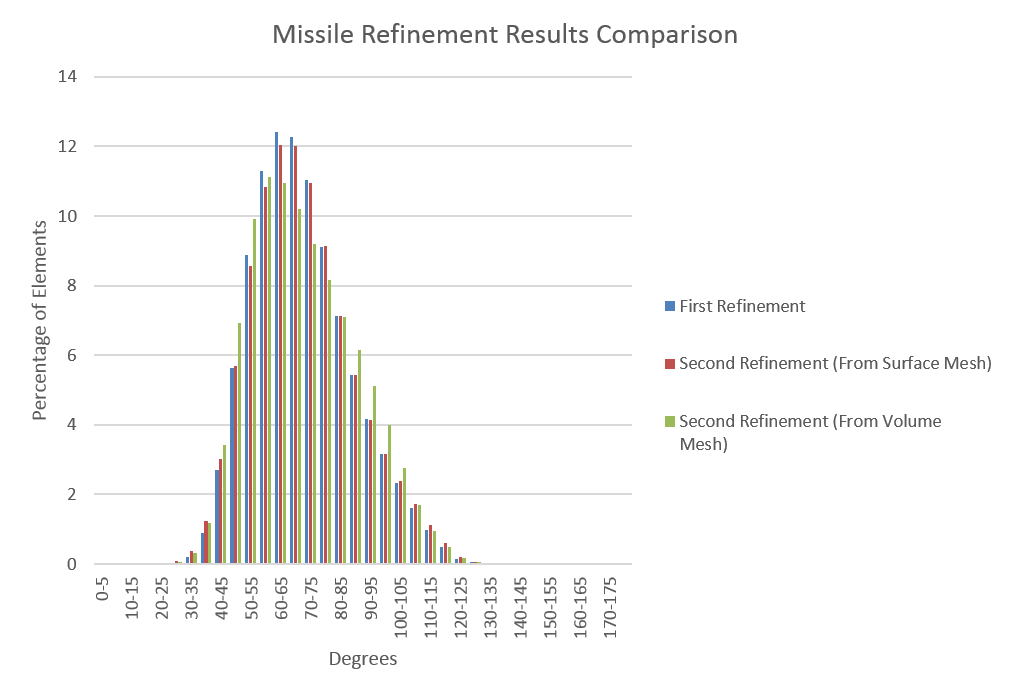
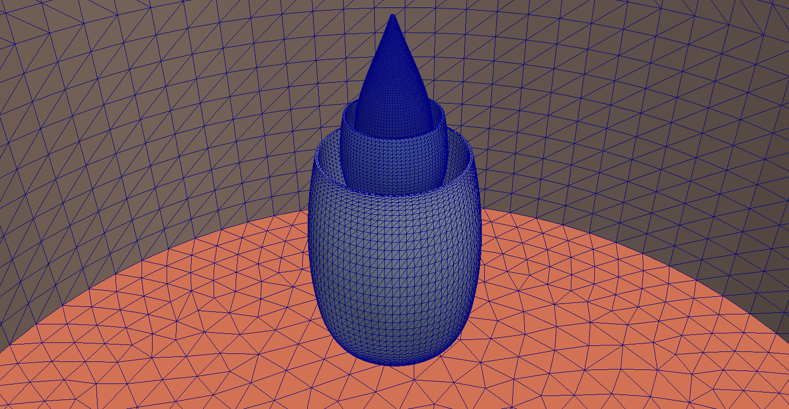
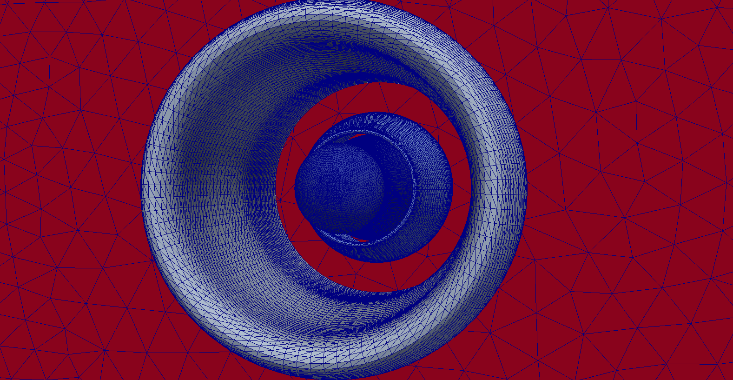
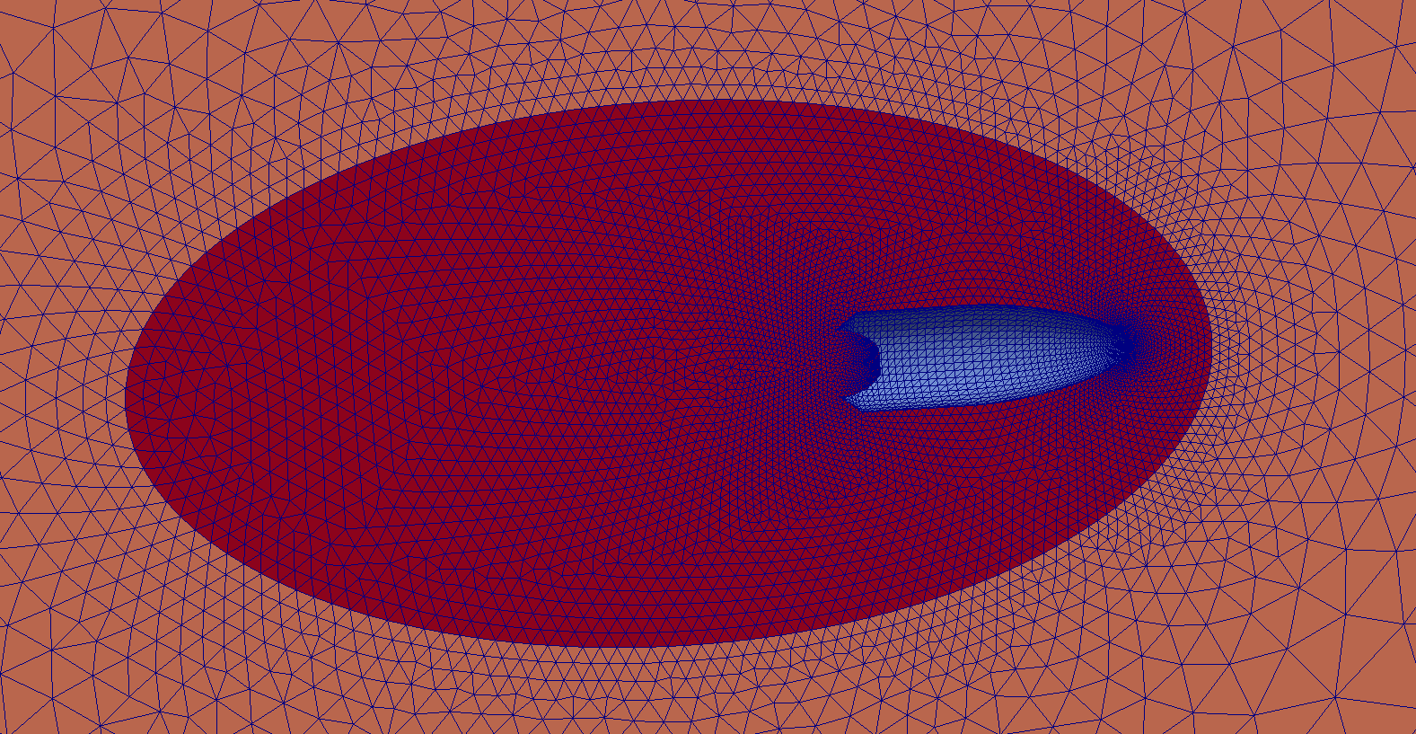
AFLR meets the reproducibility requirement of PDR, as it maintains weak reproducibility (which can be seen in the below example of refinement for the missile geometry). More examples are shown here.
Stability
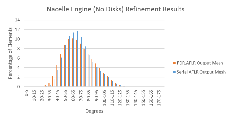
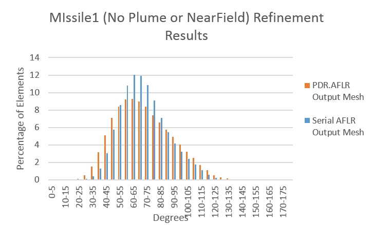
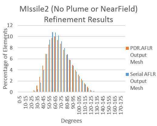
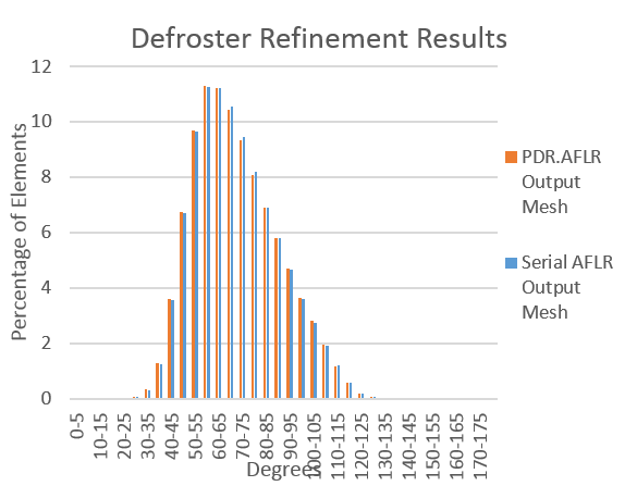
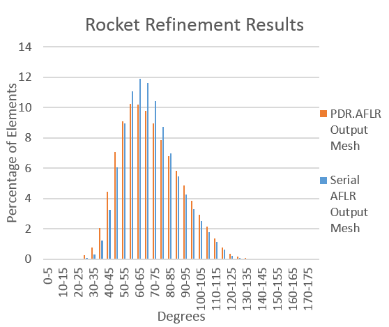
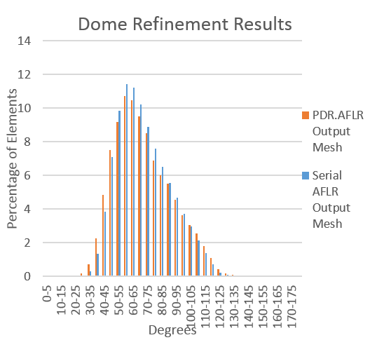
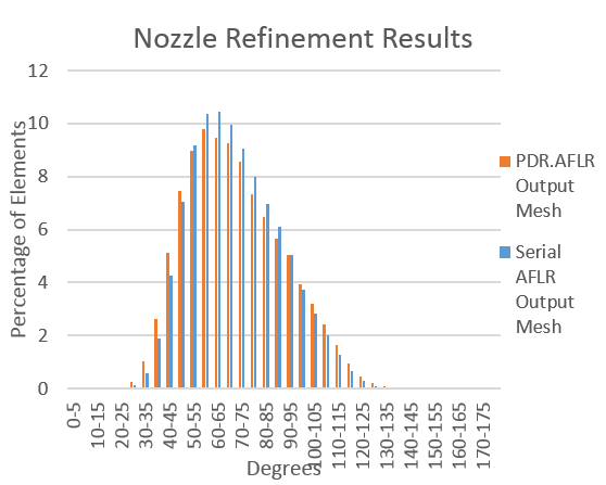
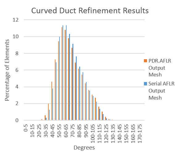
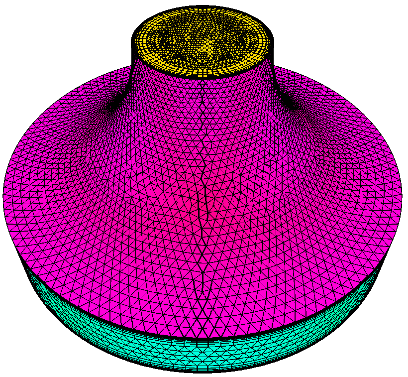
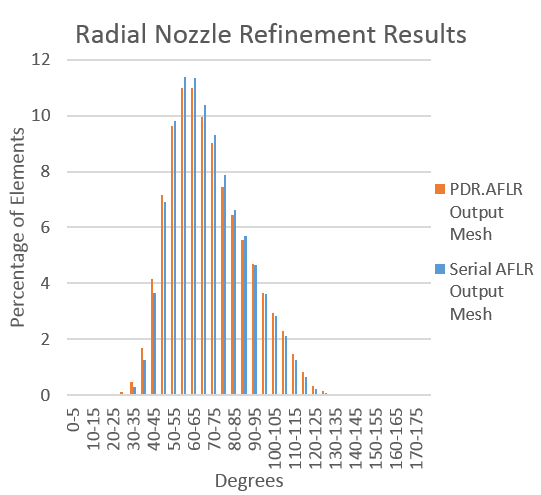
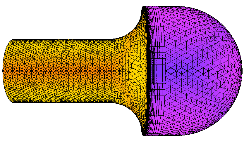
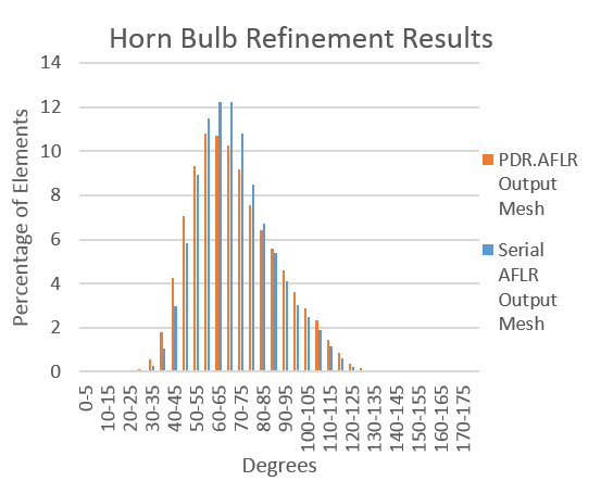
Preliminary results from the initial implementation of the sequential, data-decomposed AFLR show that PDR’s data decomposition does not hinder the quality of the output as it can be seen from the below quality statistics of meshes in comparison to their quality when generated by the serial AFLR. The bar charts show that while the output meshes of the modified AFLR contain slightly more elements of lower quality (percentage of elements towards both ends of the charts), it maintains its stability with a close number of high quality elements to that of the serial AFLR. This implementation is limited to the refinement of manifold, genus zero geometries and will be extended to more complex geometries to satisfy the robustness requirement of PDR in the final version of PDR.AFLR. It is also unable to refine meshes with transparent/embedded surfaces. This will also be addressed in the final version of PDR.AFLR. For simplicity, any transparent/embedded surfaces were removed from certain geometries while testing the stability of the data-decomposed AFLR. This is specified for specific geometries below.
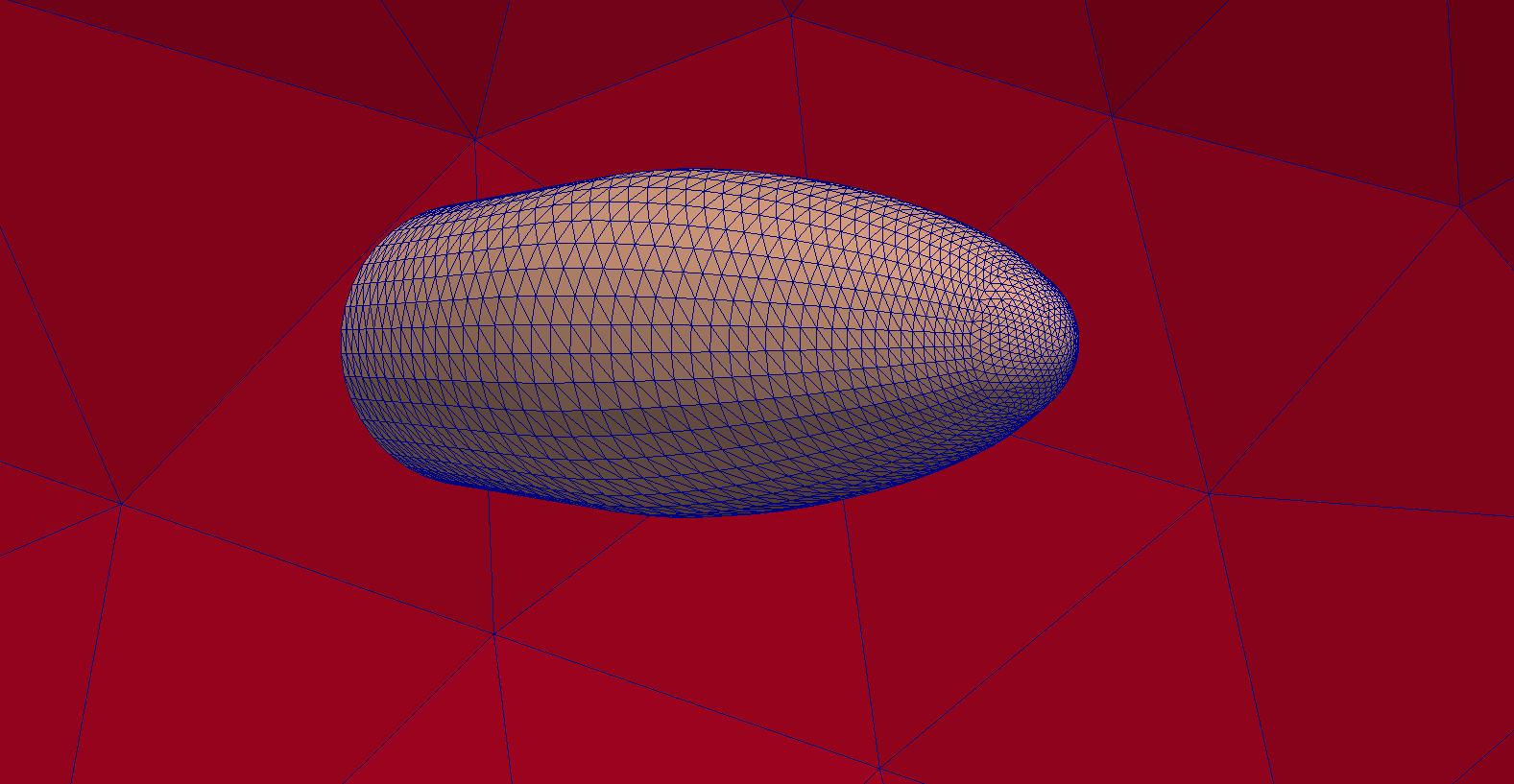
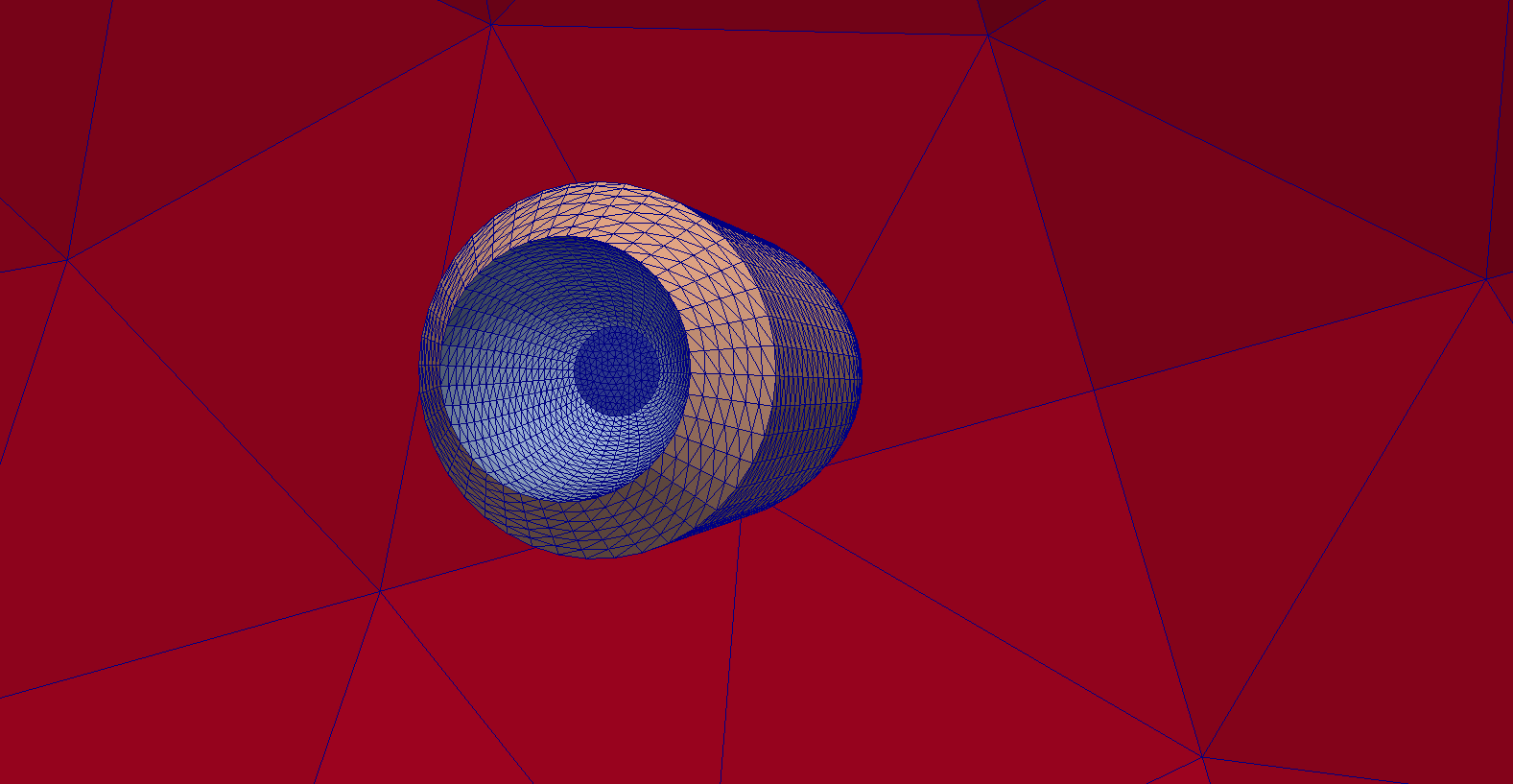
- The Fan and Turbine Disk surfaces were removed from the nacelle engine geometry. (a) and (b) show different viewpoints of the geometry. (c) compares the dihedral angle distributions of the output meshes between serial AFLR and PDR.AFLR.
- The Plume and NearField embedded surfaces were removed from the missile1 geometry. (a) and (b) show different viewpoints of the geometry. (c) compares the dihedral angle distributions of the output meshes between serial AFLR and PDR.AFLR.
- The Plume and NearField embedded surfaces were removed from the missile2 geometry.(a) shows the modified missile2 geometry. (b) shows the dihedral angle distributions of the output meshes compared between the serial AFLR code and PDR.AFLR.
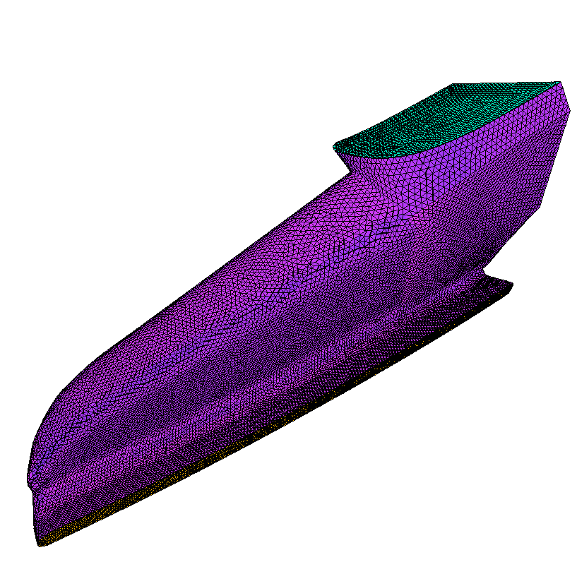
- (a) shows the defroster geometry. (b) shows the dihedral angle distributions of the output meshes compared between the serial AFLR code and PDR.AFLR.
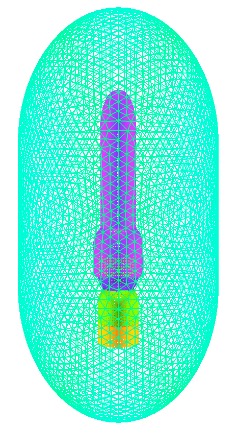
- (a) shows the rocket geometry. (b) shows the dihedral angle distributions of the output meshes compared between the serial AFLR code and PDR.AFLR.
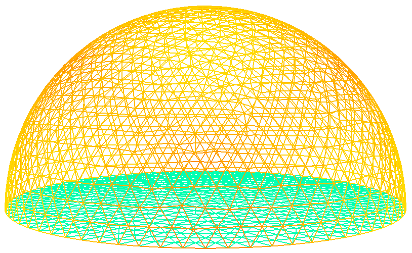
- (a) shows the dome geometry. (b) shows the dihedral angle distributions of the output meshes compared between the serial AFLR code and PDR.AFLR.
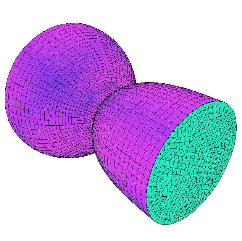
- (a) shows the nozzle geometry. (b) shows the dihedral angle distributions of the output meshes compared between the serial AFLR code and PDR.AFLR.
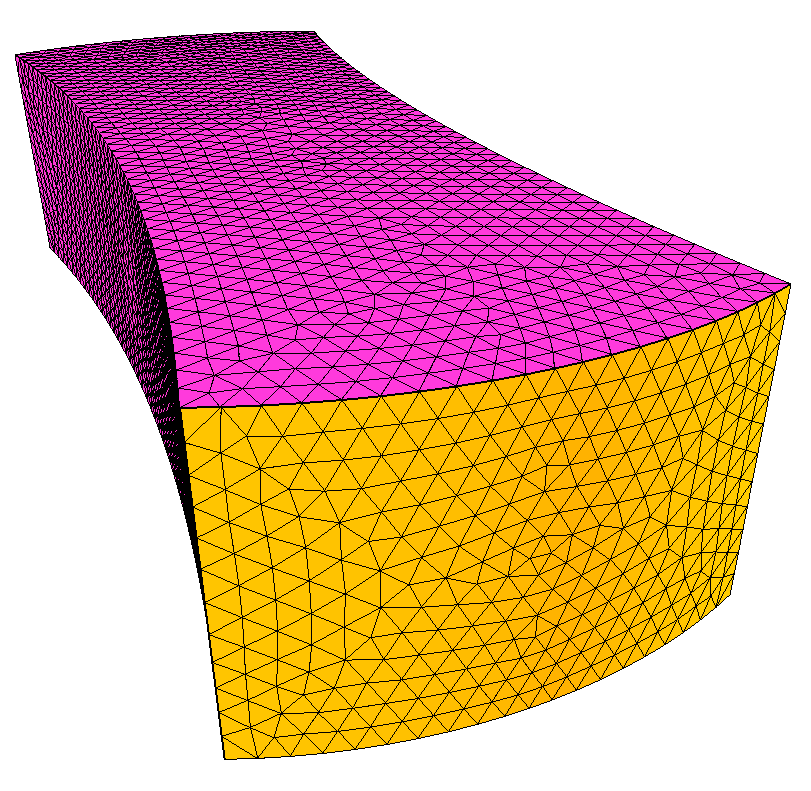
- (a) shows the curved duct geometry. (b) shows the dihedral angle distributions of the output meshes compared between the serial AFLR code and PDR.AFLR.
- (a) shows the radial nozzle geometry. (b) shows the dihedral angle distributions of the output meshes compared between the serial AFLR code and PDR.AFLR.
- (a) shows the horn bulb geometry. (b) shows the dihedral angle distributions of the output meshes compared between the serial AFLR code and PDR.AFLR.
Scalability
The parallelization of AFLR is currently a work-in-progress. During runtime, the PDR.AFLR method will expose data decomposition information (number of subdomains waiting to be refined) to our underlying run-time system, PREMA 2.0. In turn, PREMA 2.0 will facilitate work-load balancing and guide the program’s execution towards the most efficient utilization of hardware resources. PREMA 2.0 is a parallel runtime system that supports one-sided communication, global address space and load balancing for adaptive and irregular applications. This runtime system serves as an underlying layer that alleviates the burden of monitoring data and computations in parallel, an ideal candidate to support the execution of PDR.AFLR.
