Difference between revisions of "Isotropic Mesh Generation"
(→nacelle, rocket, and lv2b pg. 122-124) |
(→more nacelle, rocket, and lv2b pg. 125-127) |
||
| Line 132: | Line 132: | ||
== more nacelle, rocket, and lv2b pg. 125-127 == | == more nacelle, rocket, and lv2b pg. 125-127 == | ||
<div><ul> | <div><ul> | ||
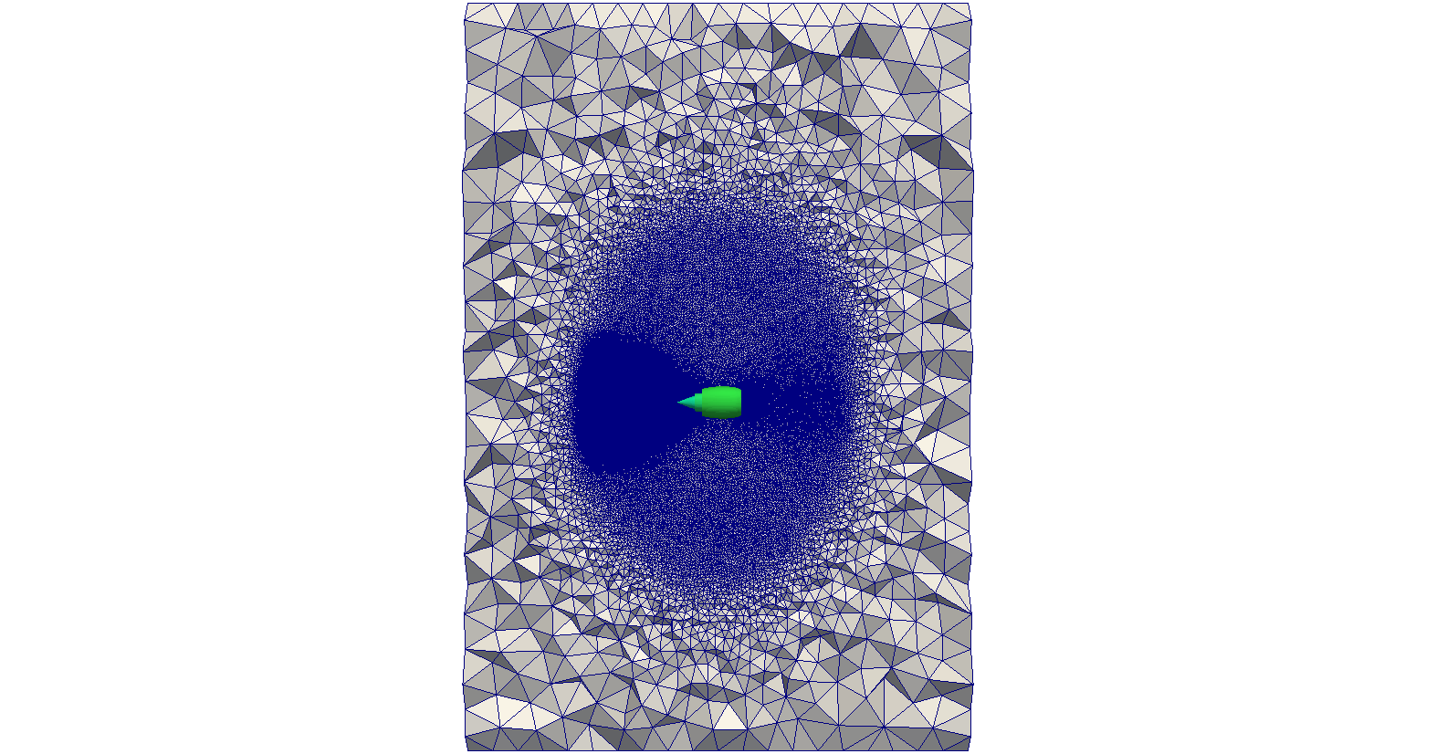
| − | <li style="display: inline-block;"> [[File: nacelleCDT3D.png|thumb|none| | + | <li style="display: inline-block;"> [[File: nacelleCDT3D.png|thumb|none|750px|''(a) CDT3D: 42.85 M tetrahedra'']] </li> |
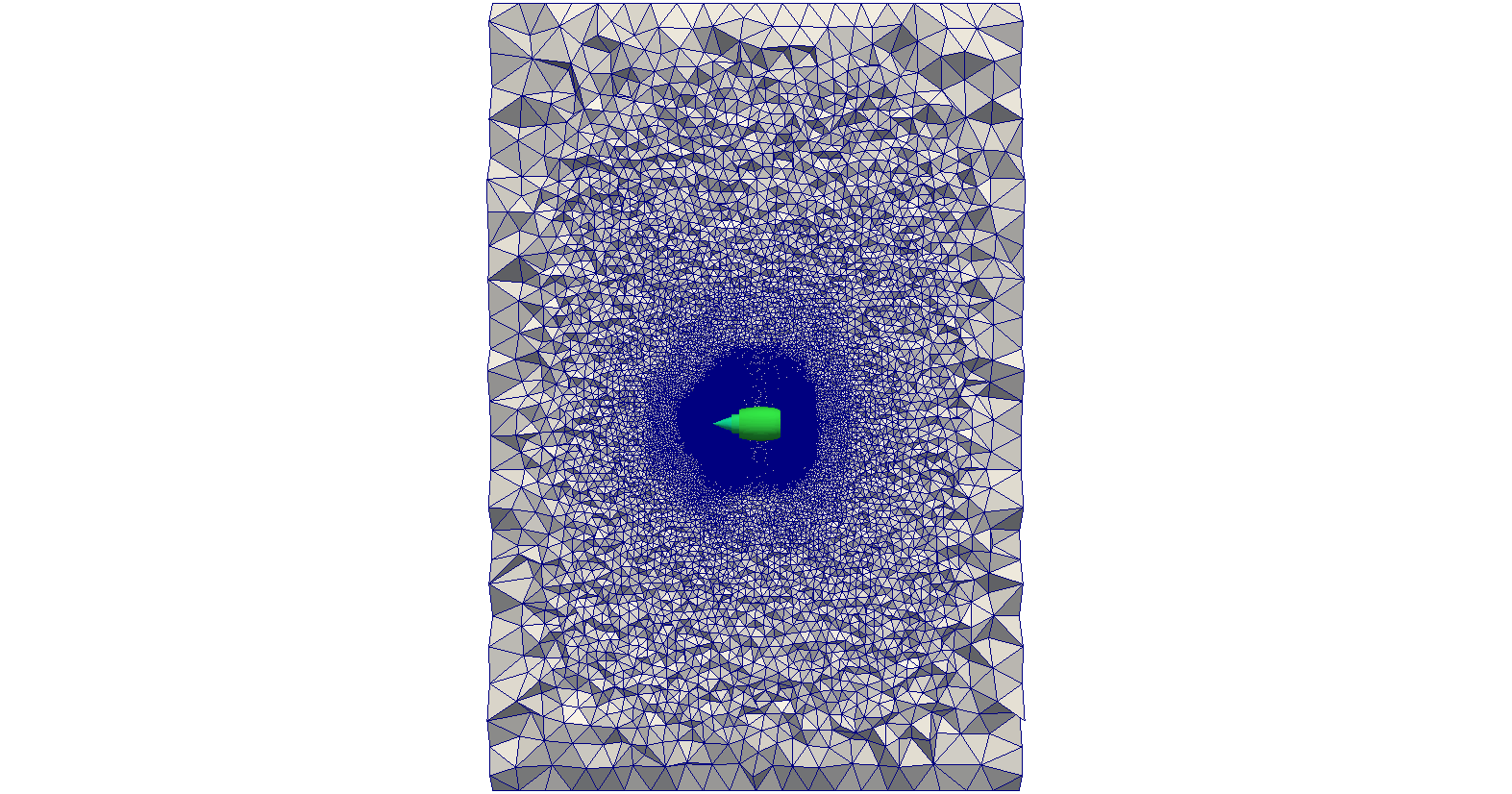
| − | <li style="display: inline-block;"> [[File: nacelleAFLR.png|thumb|none| | + | <li style="display: inline-block;"> [[File: nacelleAFLR.png|thumb|none|750px|''(b) AFLR: 39.64 M tetrahedra'']] </li> |
</ul></div> | </ul></div> | ||
| + | |||
| + | :Tetrahedral field cuts of the aircraft nacelle | ||
| + | <br><br><br> | ||
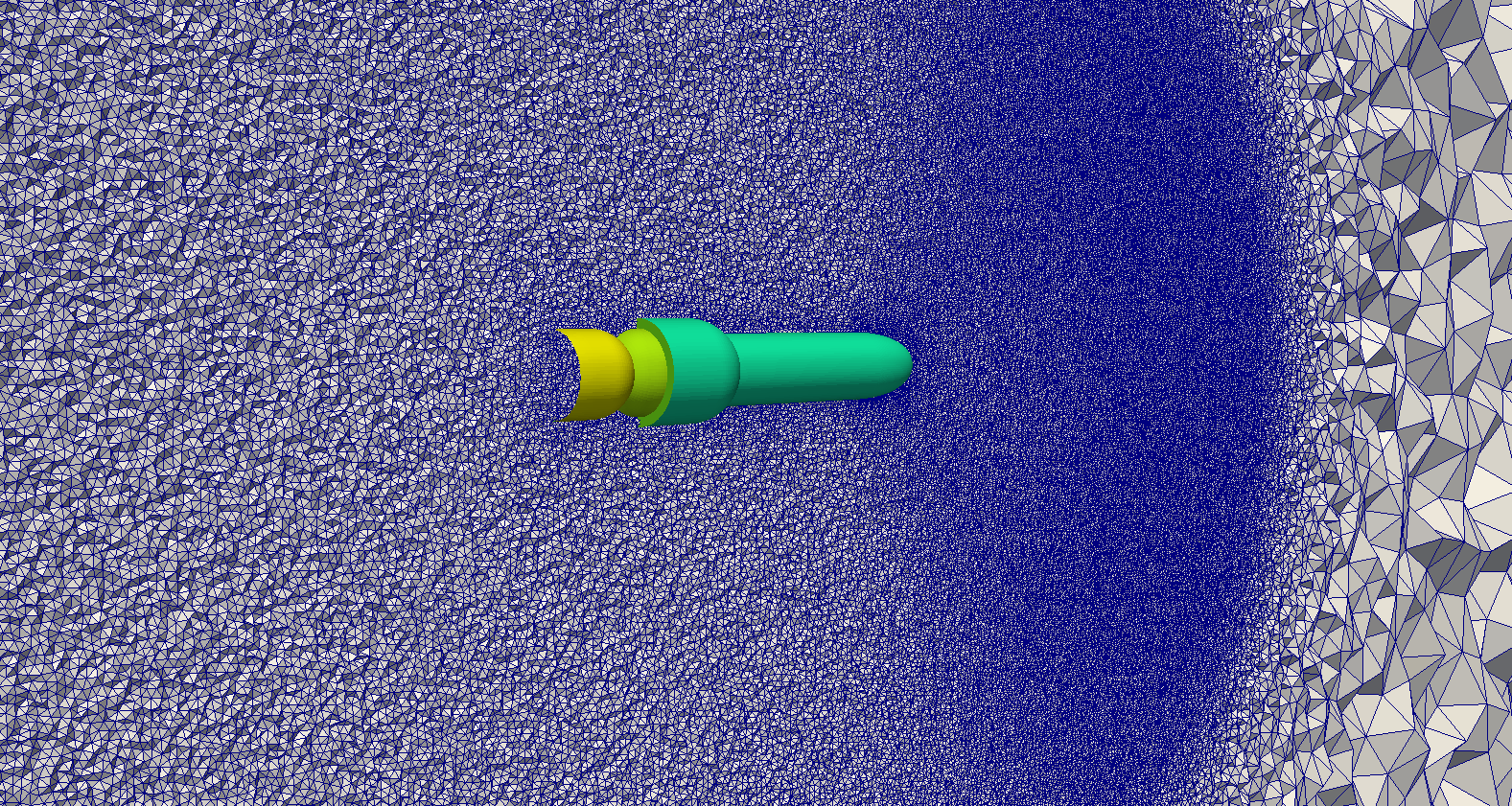
<div><ul> | <div><ul> | ||
| − | <li style="display: inline-block;"> [[File: nacelle5_small.png|thumb|none|650px | + | <li style="display: inline-block;"> [[File: nacelle5_small.png|thumb|none|650px]] </li> |
| − | <li style="display: inline-block;"> [[File: nacelle9.png|thumb|none|650px | + | <li style="display: inline-block;"> [[File: nacelle9.png|thumb|none|650px]] </li> |
</ul></div> | </ul></div> | ||
| + | |||
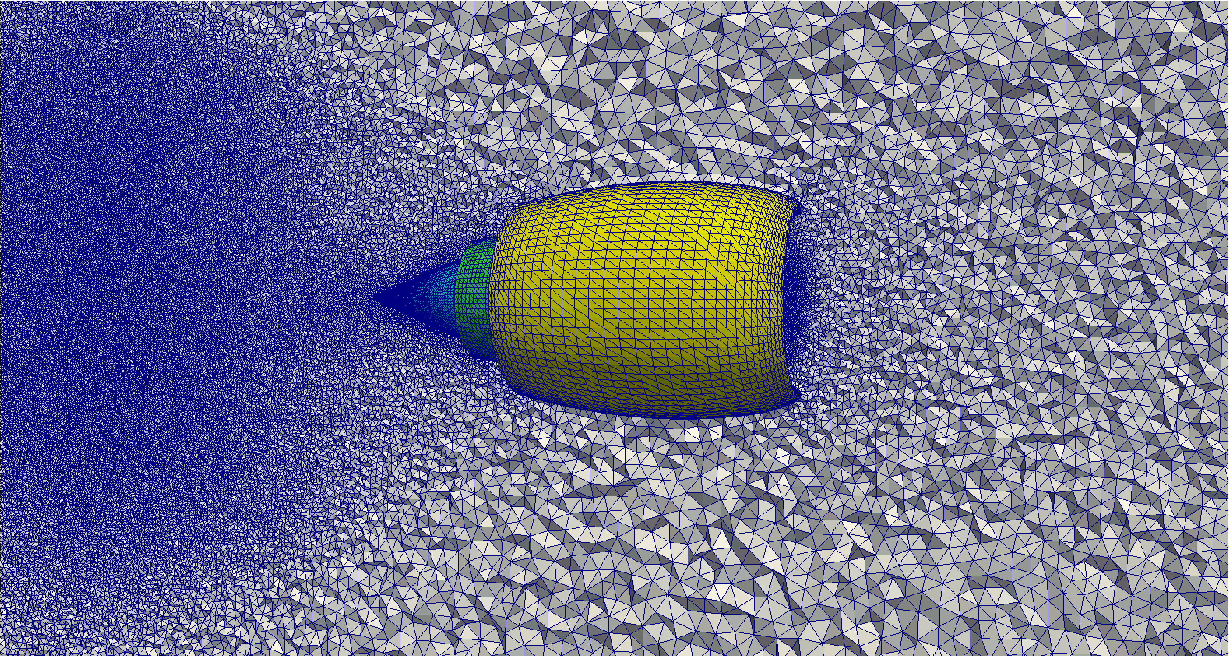
| + | :Detail views of tetrahedral field cuts of aircraft nacelle generated with CDT3D | ||
| + | <br><br><br> | ||
<div><ul> | <div><ul> | ||
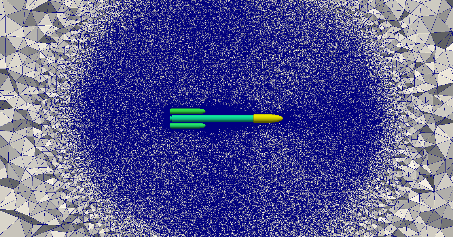
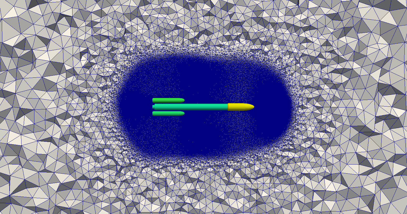
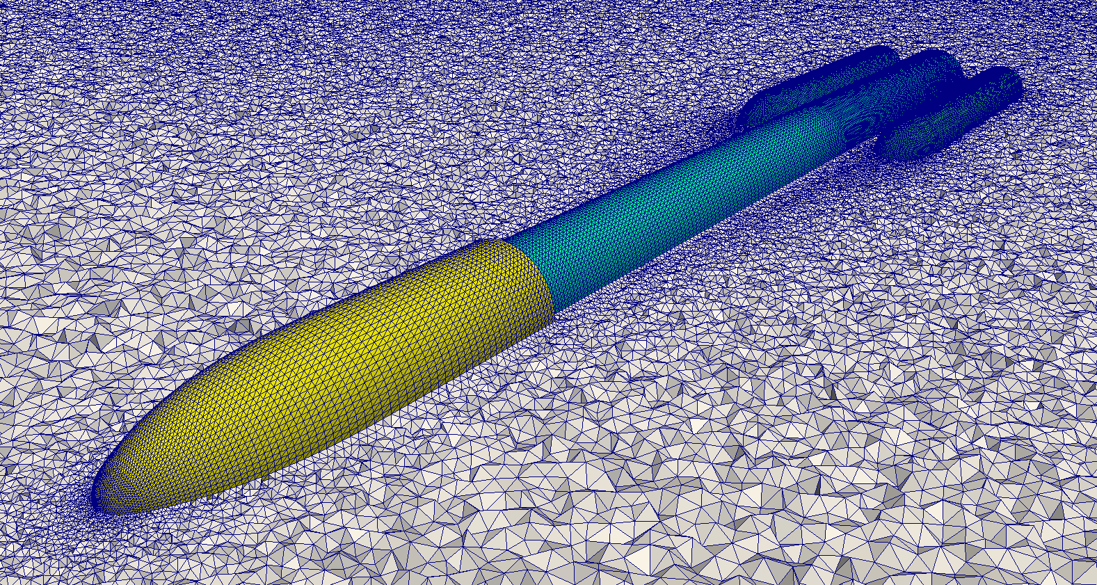
| − | <li style="display: inline-block;"> [[File: rocketCDT3D.png|thumb|none|650px|'' | + | <li style="display: inline-block;"> [[File: rocketCDT3D.png|thumb|none|650px|''(a) CDT3D: 119.06 M tetrahedra'']] </li> |
| − | <li style="display: inline-block;"> [[File: rocketAFLR.png|thumb|none|650px|'' | + | <li style="display: inline-block;"> [[File: rocketAFLR.png|thumb|none|650px|''(b) AFLR: 127.68 M tetrahedra'']] </li> |
</ul></div> | </ul></div> | ||
| − | |||
<div><ul> | <div><ul> | ||
| − | <li style="display: inline-block;"> [[File: rocket5.png|thumb|none|650px|'' | + | <li style="display: inline-block;"> [[File: rocket5.png|thumb|none|650px|''(c) Detail view of (a)'']] </li> |
| − | <li style="display: inline-block;"> [[File: rocket9.png|thumb|none|650px|'' | + | <li style="display: inline-block;"> [[File: rocket9.png|thumb|none|650px|''(d) Detail view of (a)'']] </li> |
</ul></div> | </ul></div> | ||
| + | |||
| + | :Tetrahedral field cuts of the rocket | ||
| + | <br><br><br> | ||
<div><ul> | <div><ul> | ||
| − | <li style="display: inline-block;"> [[File: lv2bCDT3D.png|thumb|none|650px|'' | + | <li style="display: inline-block;"> [[File: lv2bCDT3D.png|thumb|none|650px|''(a) CDT3D: 110.01 M tetrahedra'']] </li> |
| − | <li style="display: inline-block;"> [[File: lv2bAFLR.png|thumb|none|650px|'' | + | <li style="display: inline-block;"> [[File: lv2bAFLR.png|thumb|none|650px|''(b) AFLR: 100.92 M tetrahedra'']] </li> |
</ul></div> | </ul></div> | ||
| − | |||
<div><ul> | <div><ul> | ||
| − | <li style="display: inline-block;"> [[File: lv2b7.png|thumb|none|650px|'' | + | <li style="display: inline-block;"> [[File: lv2b7.png|thumb|none|650px|''(c) Detail view of (a)'']] </li> |
| − | <li style="display: inline-block;"> [[File: lv2b8.png|thumb|none|650px|'' | + | <li style="display: inline-block;"> [[File: lv2b8.png|thumb|none|650px|''(d) Detail view of (a)'']] </li> |
</ul></div> | </ul></div> | ||
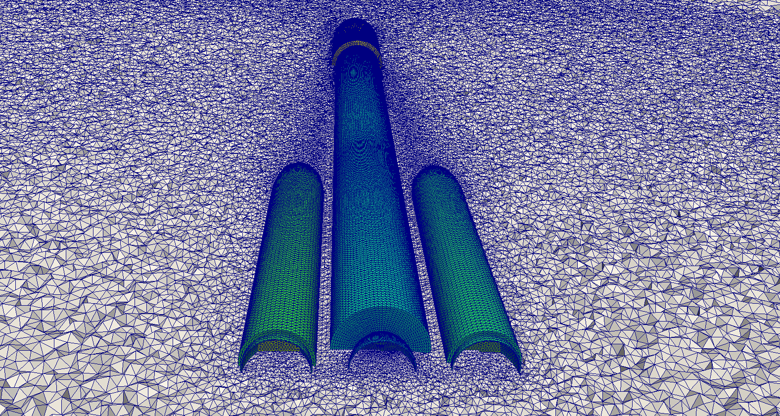
| + | Tetrahedral field cuts of the Lv2b | ||
| + | <br><br><br> | ||
<div><ul> | <div><ul> | ||
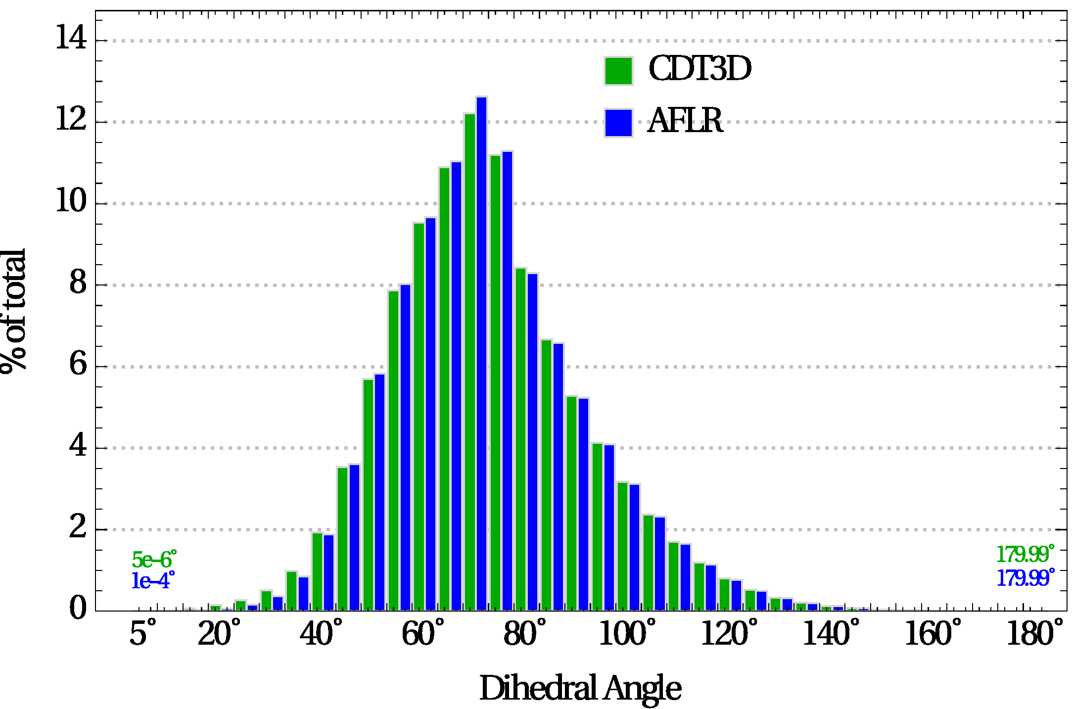
| − | <li style="display: inline-block;"> [[File: histogramNacelleNoOpt.png|thumb|none|650px|'' | + | <li style="display: inline-block;"> [[File: histogramNacelleNoOpt.png|thumb|none|650px|''(a) w/o improvement'']] </li> |
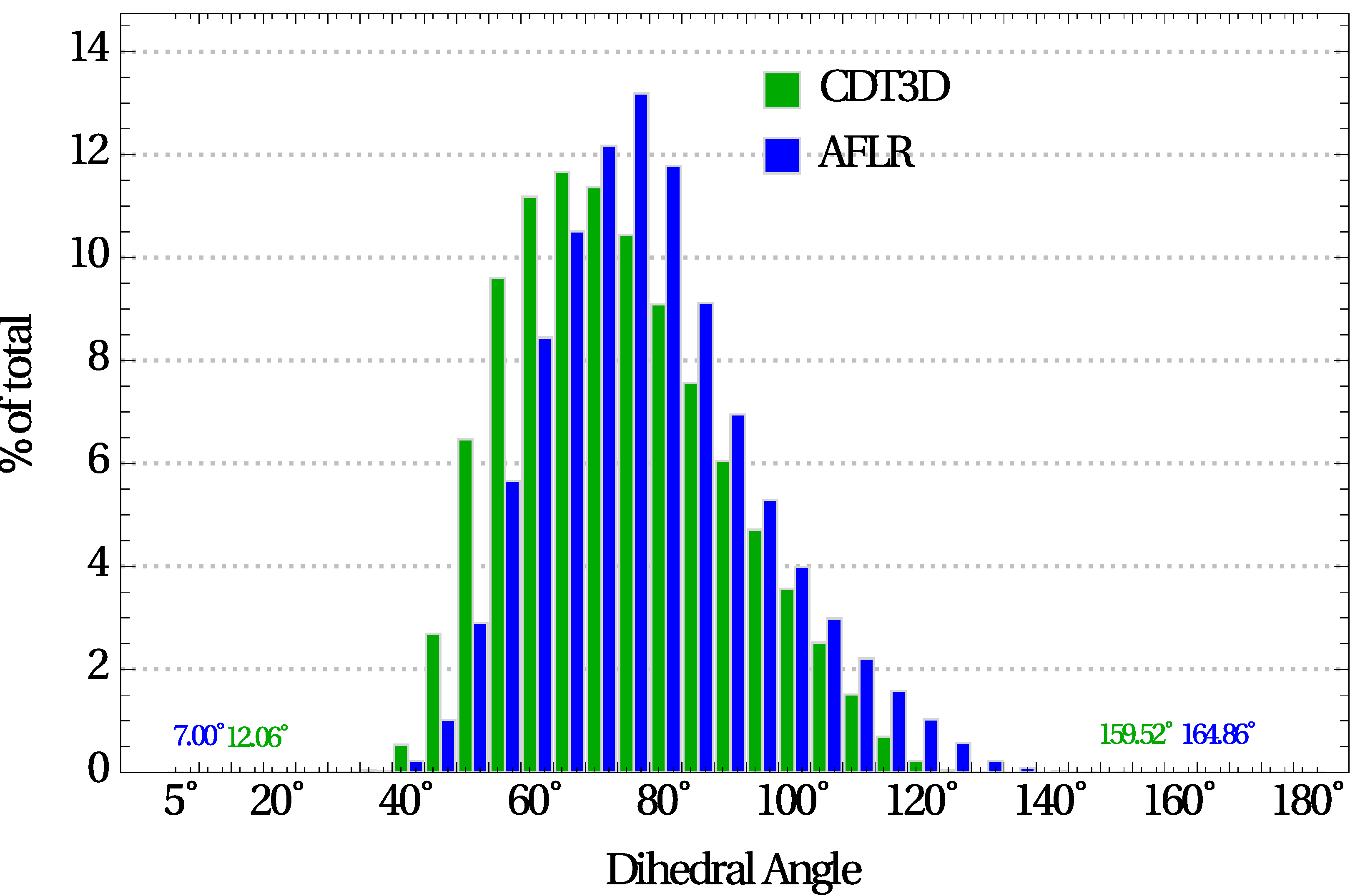
| − | <li style="display: inline-block;"> [[File: histogramNacelleOpt.png|thumb|none|650px|'' | + | <li style="display: inline-block;"> [[File: histogramNacelleOpt.png|thumb|none|650px|''(b) w/ improvement'']] </li> |
</ul></div> | </ul></div> | ||
| + | Element angle distribution (in 5-deg increments) of aircraft nacelle grids. <br>The dihedral angle extrema are reported for each method. | ||
| + | <br><br><br> | ||
<div><ul> | <div><ul> | ||
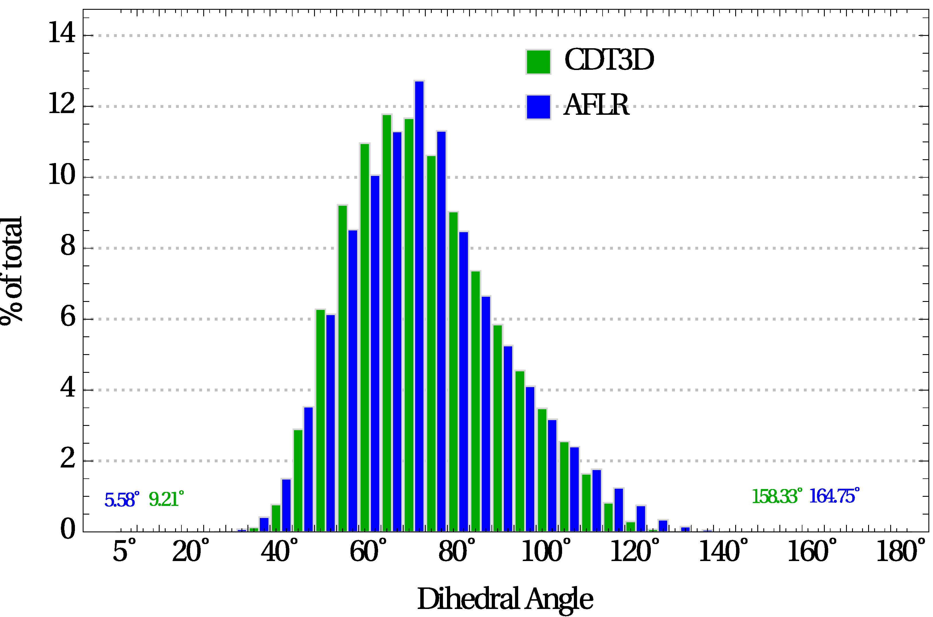
| − | <li style="display: inline-block;"> [[File: histogramRocketOpt.png|thumb|none|650px|'' | + | <li style="display: inline-block;"> [[File: histogramRocketOpt.png|thumb|none|650px|''(a) Rocket (w/ improvement)'']] </li> |
| − | <li style="display: inline-block;"> [[File: histogramLvOpt.png|thumb|none|650px|'' | + | <li style="display: inline-block;"> [[File: histogramLvOpt.png|thumb|none|650px|''(b) Lv2b (w/ improvement)'']] </li> |
</ul></div> | </ul></div> | ||
| + | Element angle distribution (in 5-deg increments) after improvement of Rocket and Lv2b grids. <br>The dihedral angle extrema are reported for each method. | ||
| + | <br><br><br> | ||
<div><ul> | <div><ul> | ||
| − | <li style="display: inline-block;"> [[File: sliversNacelleCDT3D.png|thumb|none|650px|'' | + | <li style="display: inline-block;"> [[File: sliversNacelleCDT3D.png|thumb|none|650px|''(a) CDT3D: 1590 slivers (0.0037%) out of total 42.91 M tetrahedra'']] </li> |
| − | <li style="display: inline-block;"> [[File: sliversNacelleAFLR.png|thumb|none|650px|'' | + | <li style="display: inline-block;"> [[File: sliversNacelleAFLR.png|thumb|none|650px|''(b) AFLR: 1287 slivers (0.0029%) out of total 43.23 M tetrahedra'']] </li> |
</ul></div> | </ul></div> | ||
| + | |||
| + | Slivers after the completion of refinement of the aircraft nacelle. <br>Red represents elements whose minimum dihedral angle is smaller than 2◦ or larger than 178◦. | ||
== aircraft pg. 140-142 == | == aircraft pg. 140-142 == | ||
Revision as of 12:59, 27 March 2018
Contents
Sphere and Two Blades with Merging Wakes and a Symmetry Plane
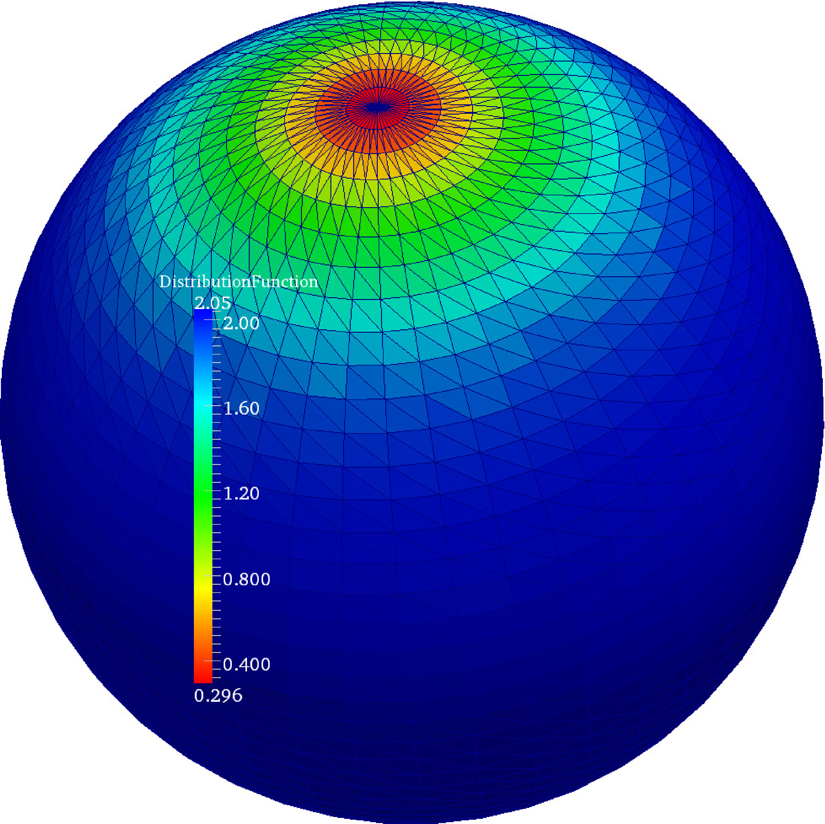
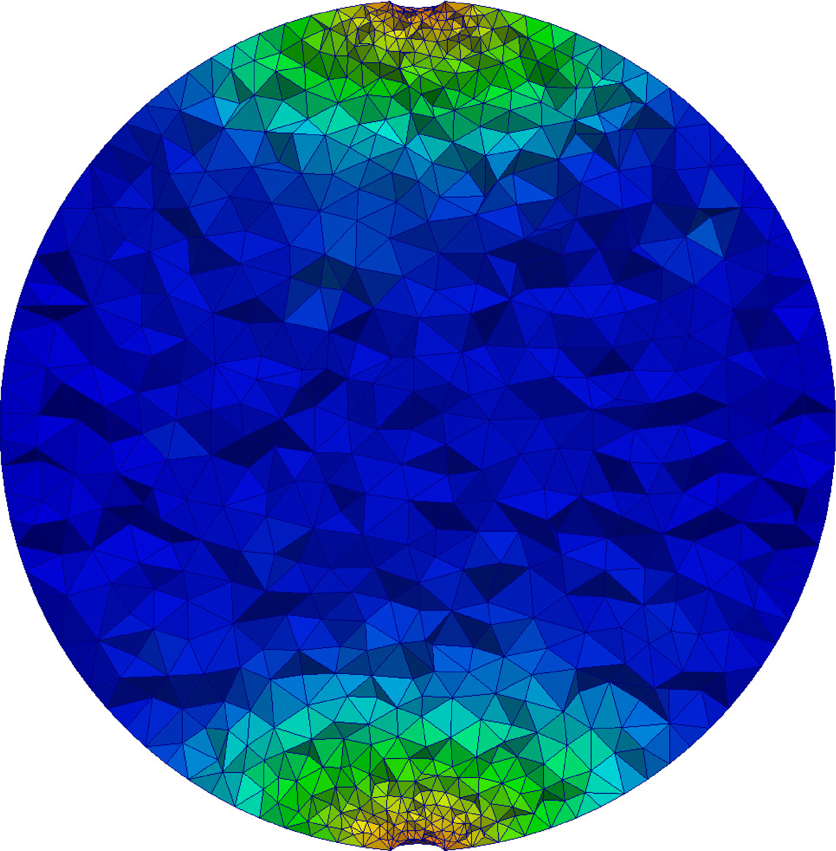
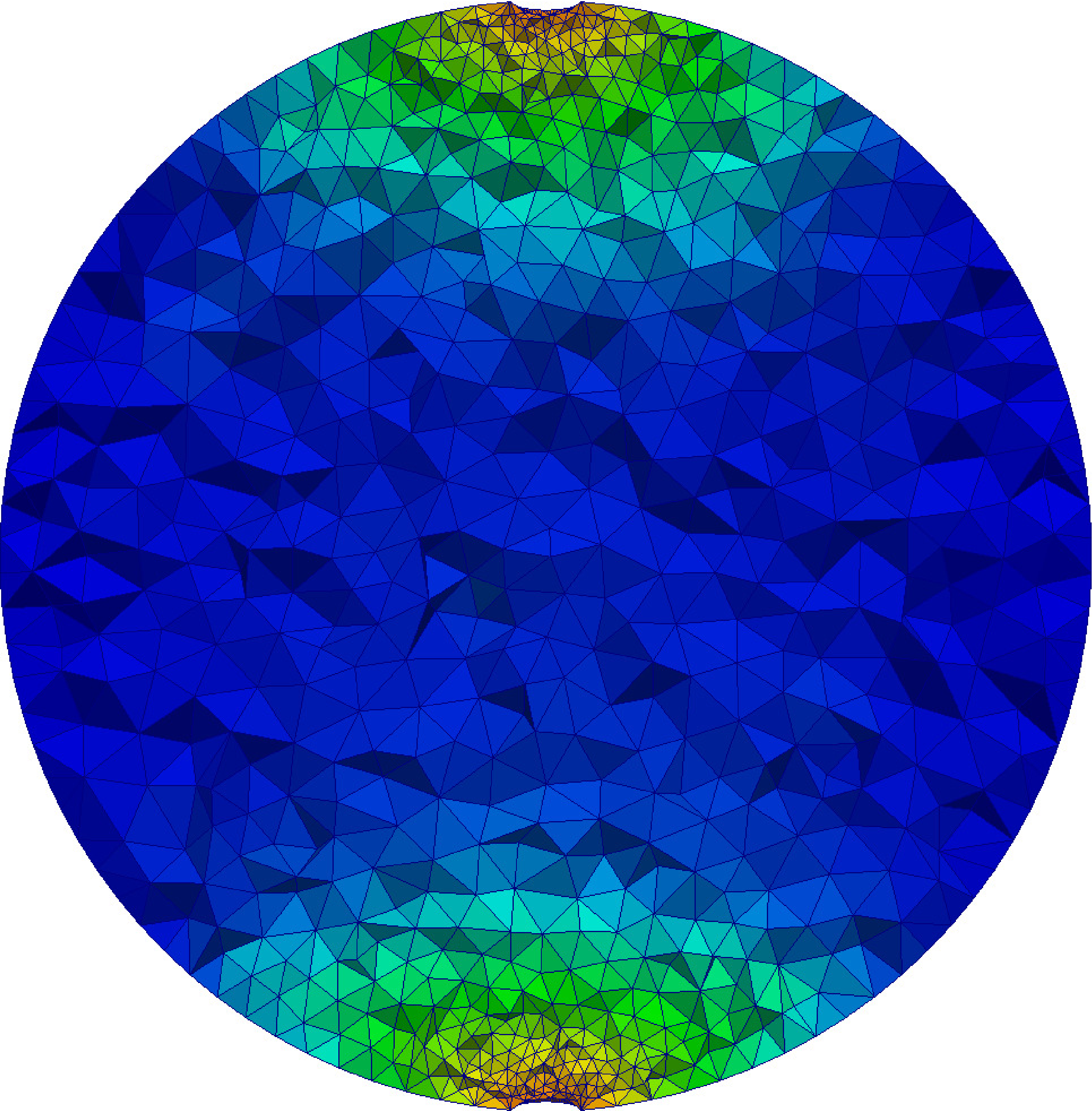
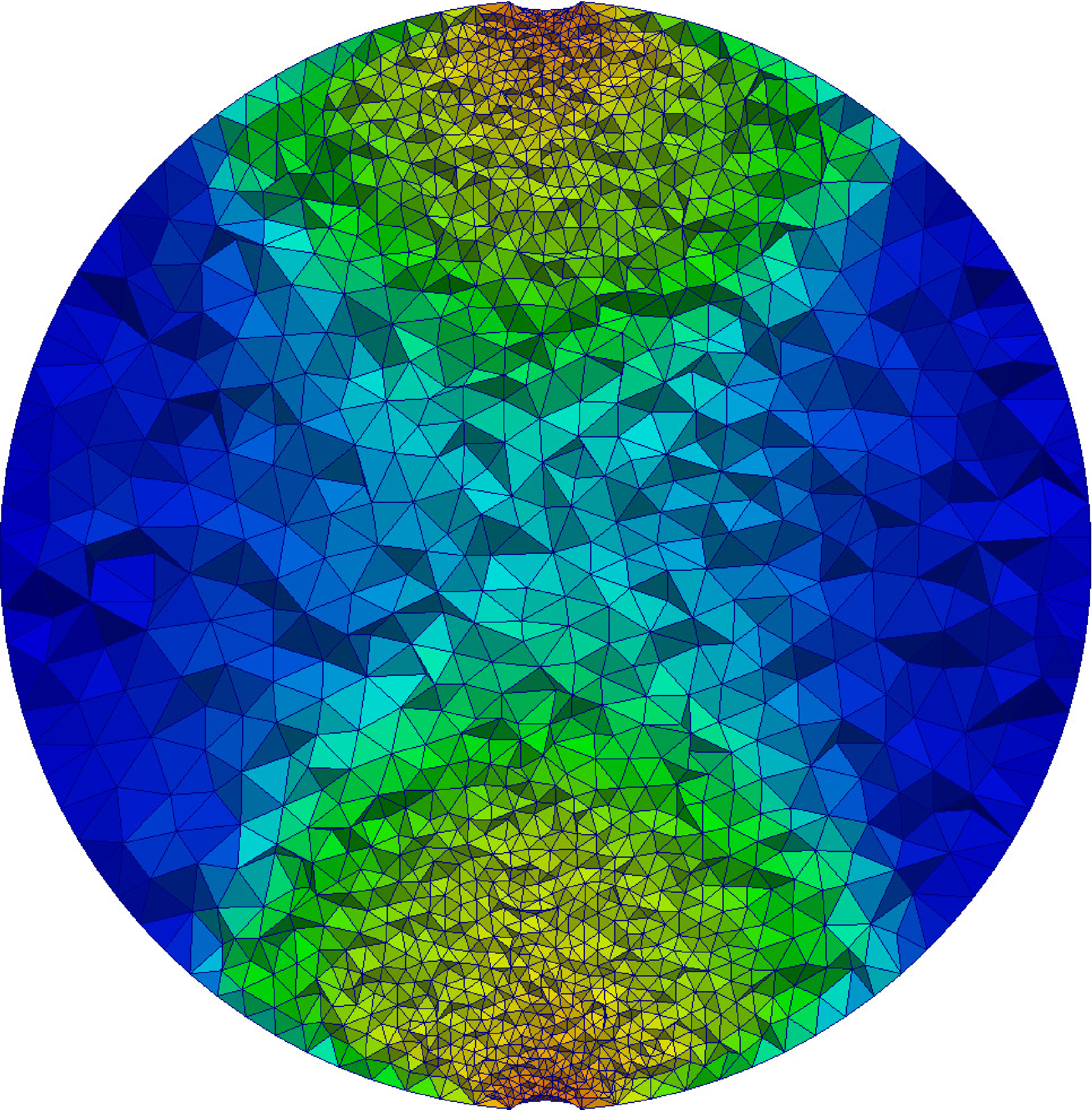
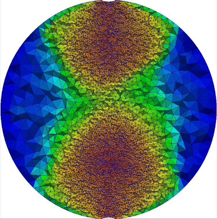
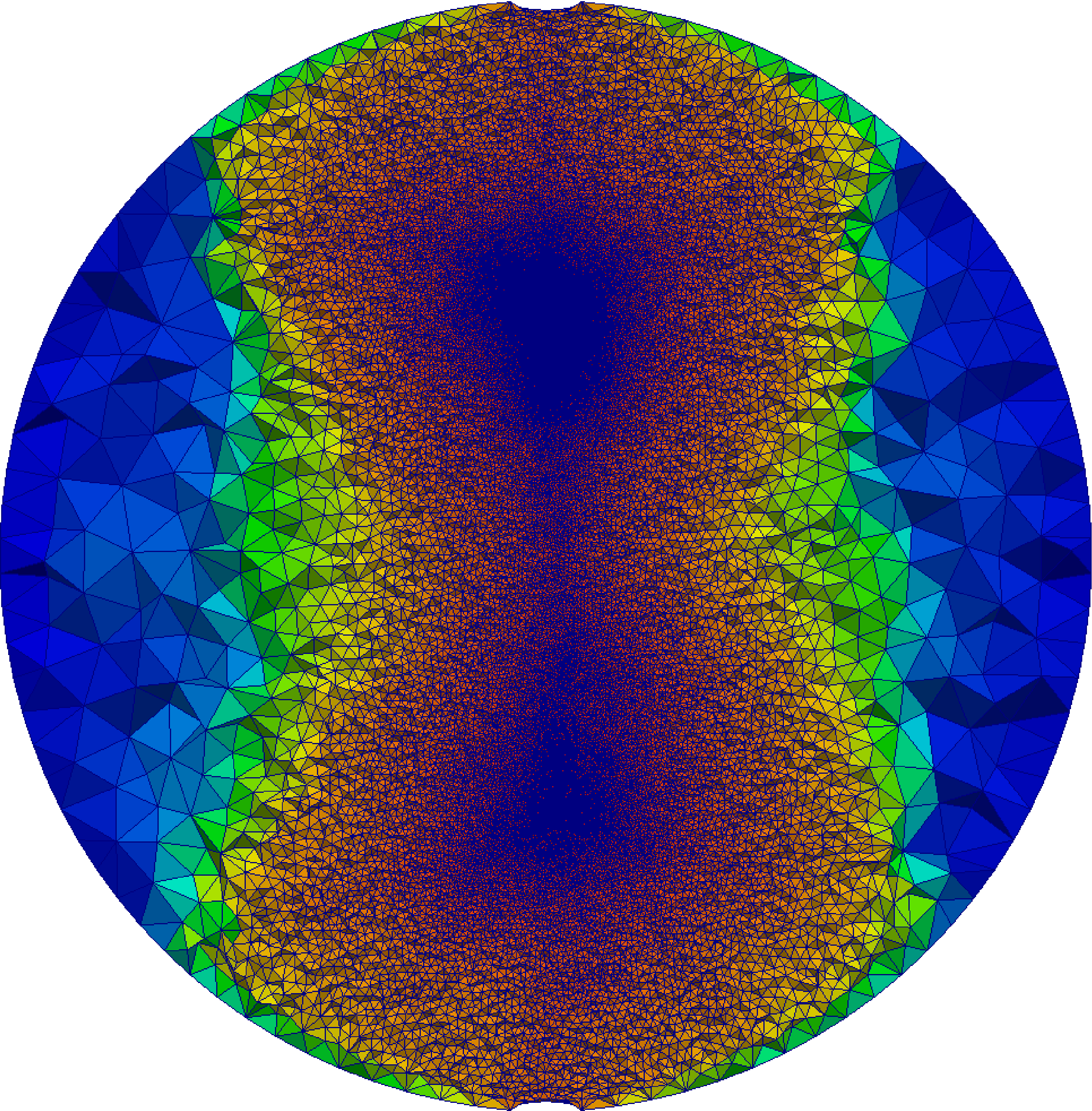
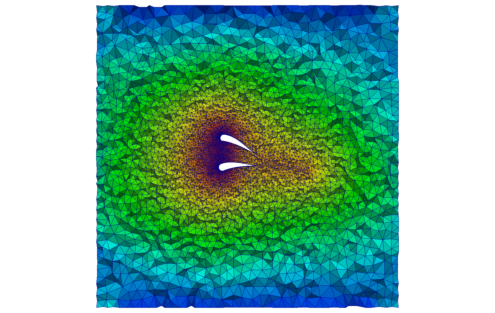
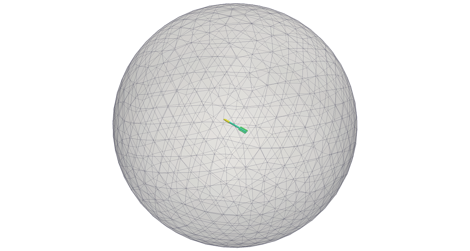
Cuts of tetrahedral grids of a sphere generated for varied cdfm ∈ [0, 1]. Blue
corresponds to larger values of the distribution function. Red corresponds to smaller values
of the distribution function.
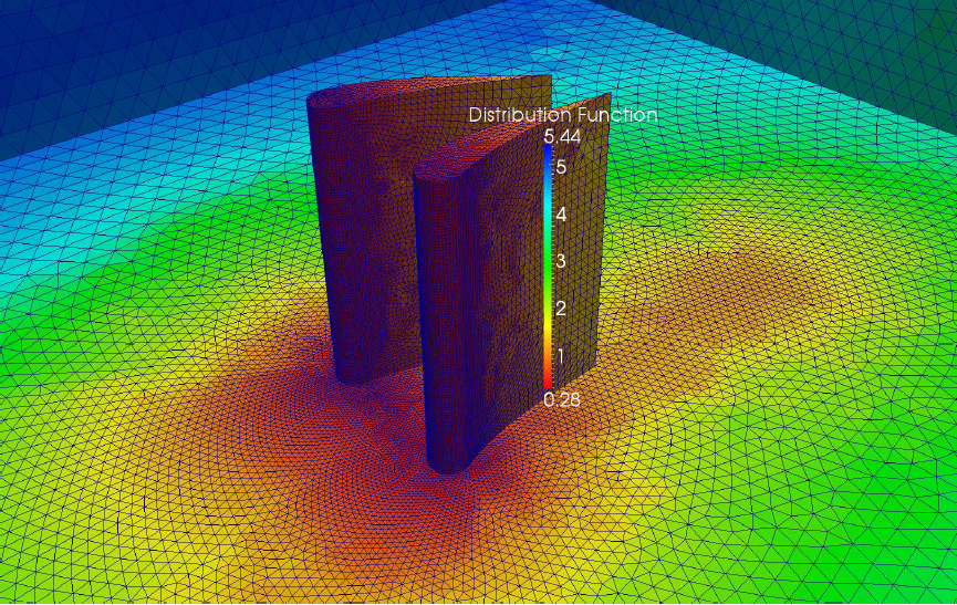
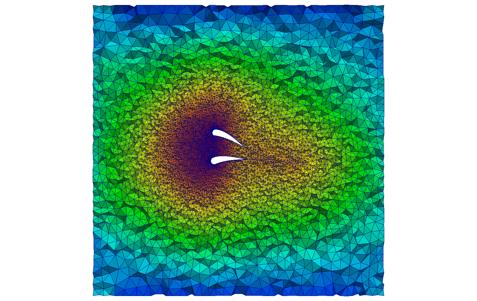
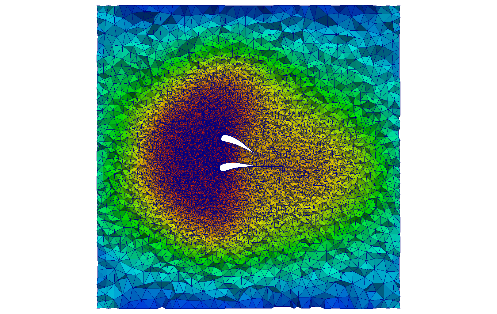
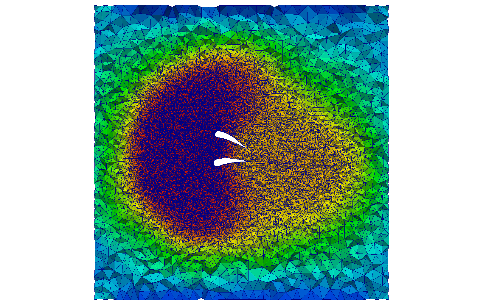
Cuts of tetrahedral grids of two blades with merging wakes and a symmetry
plane enclosed in an outer boundary generated for varied cdfm ∈ [0, 1] (shown in
(c)-(f)).
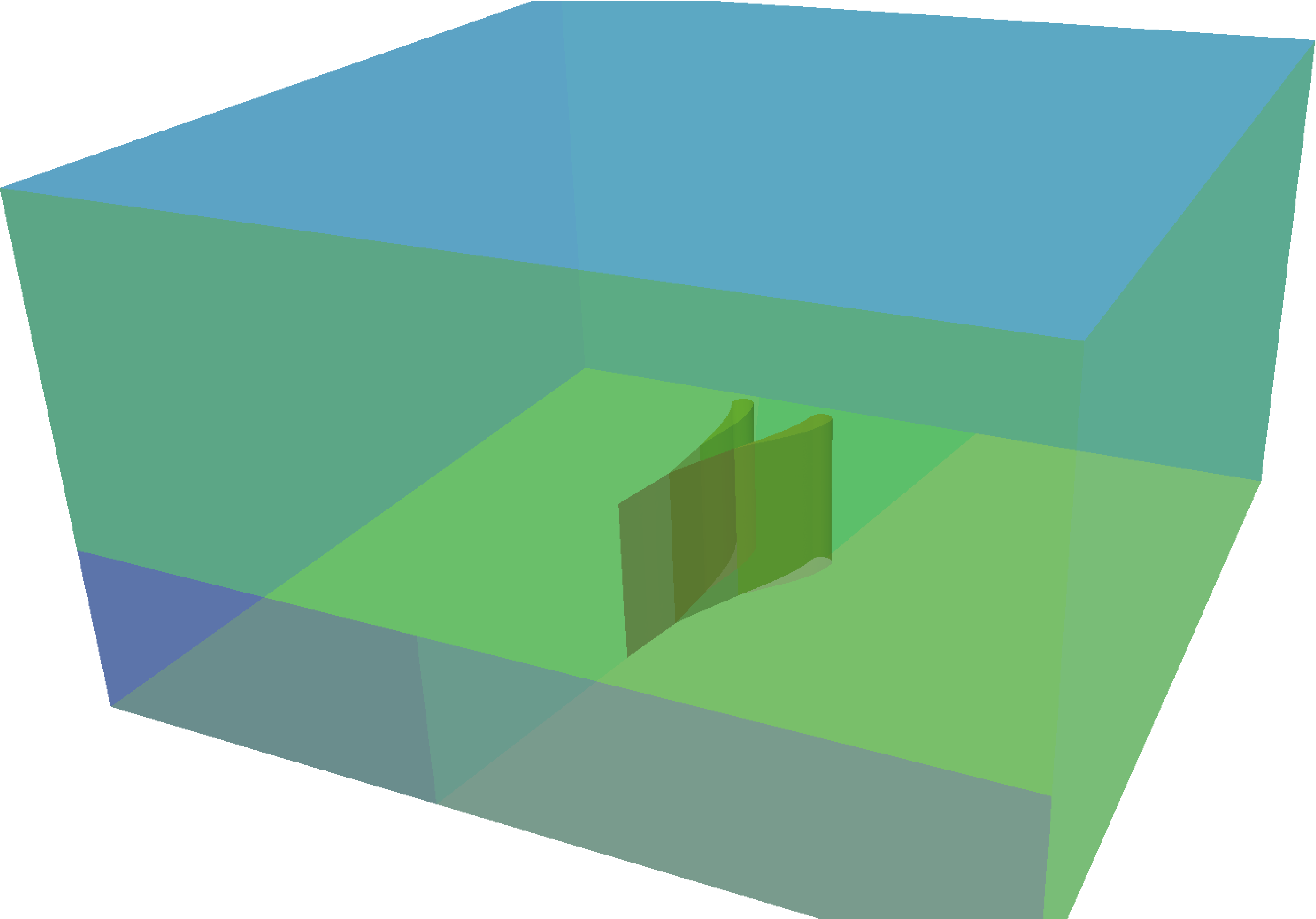
The input surface is depicted in (a)-(b). The wake region is modeled as an embedded/
transparent delete surface.
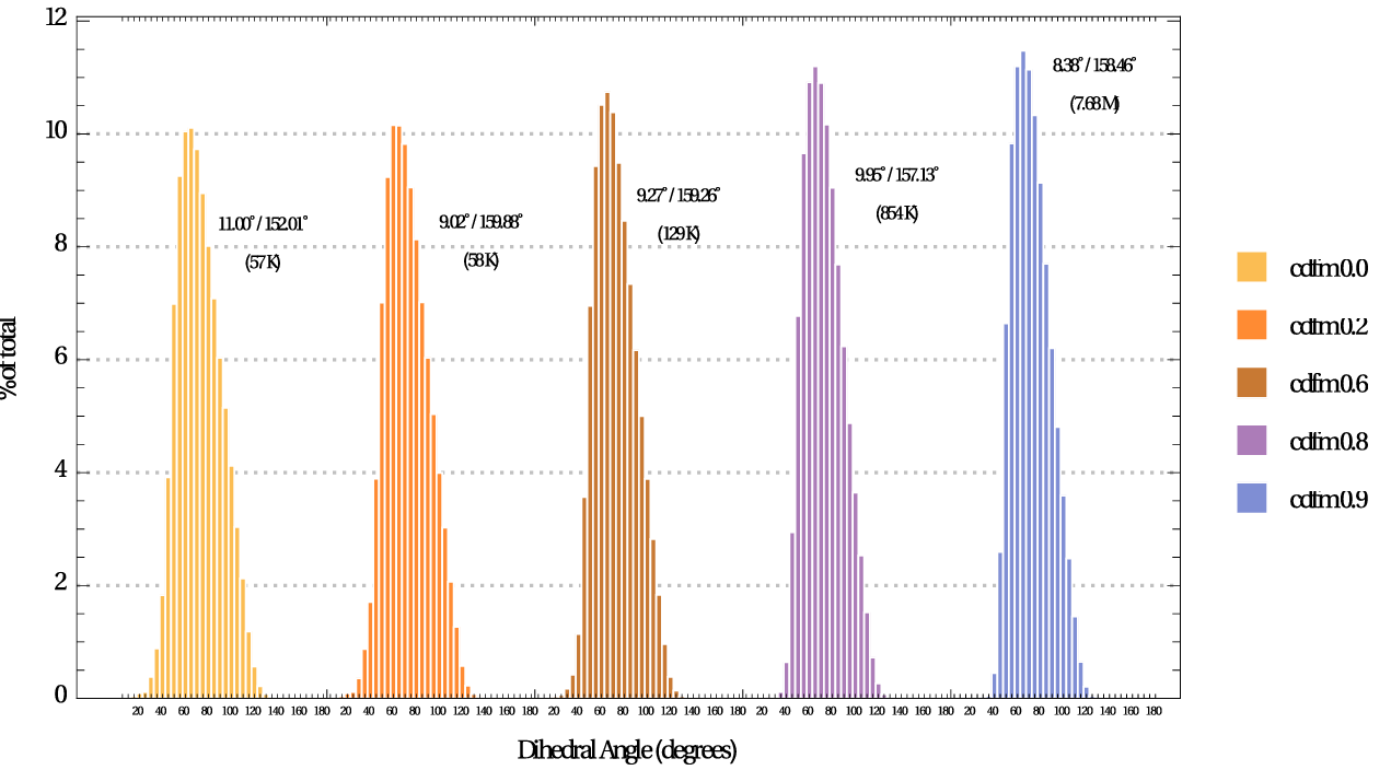
Element angle distribution (in 5-deg increments) of grids of sphere, for varied
cdfm.
The dihedral angle extrema and the element count are reported for each grid.
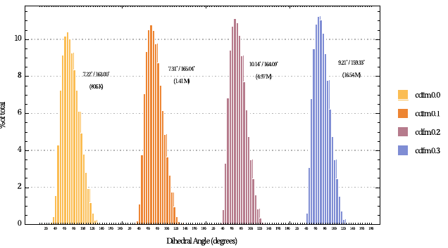
Element angle distribution (in 5-deg increments) of grids of two blades with
merging wakes and a symmetry plane enclosed in an outer boundary, for varied cdfm.
The
dihedral angle extrema and the element count are reported for each grid.
nacelle, rocket, and lv2b pg. 122-124
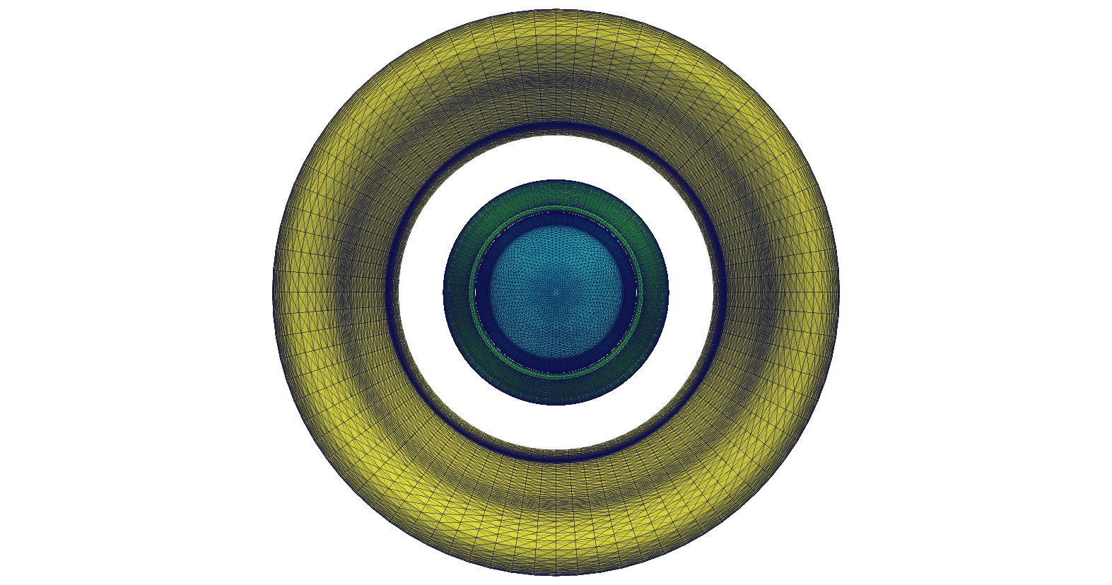
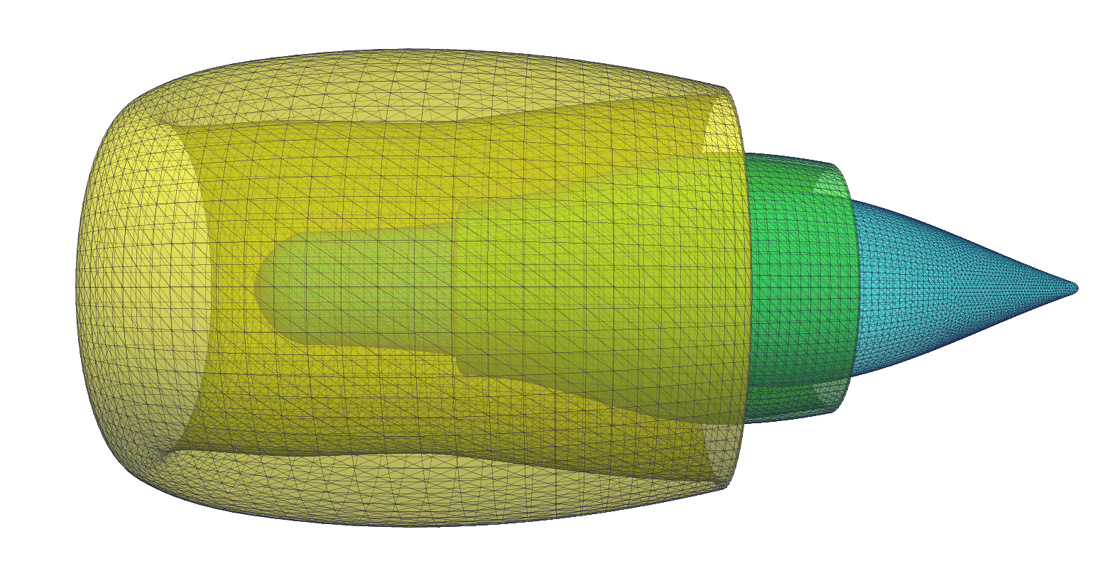
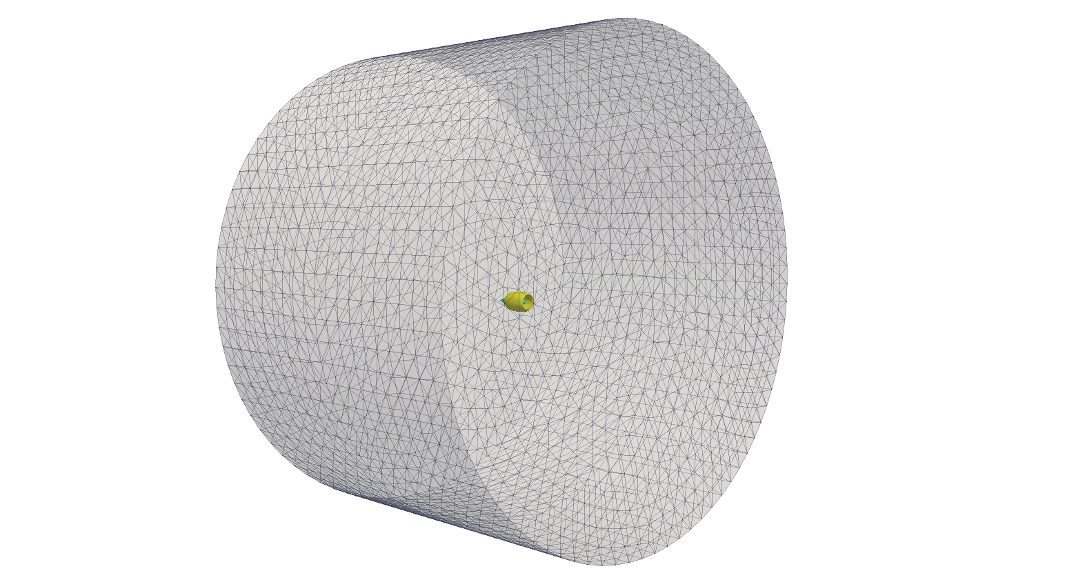
- Surface grid of an aircraft nacelle with engine inside a section of wind tunnel.
- #points: 27184; #triangles: 54360
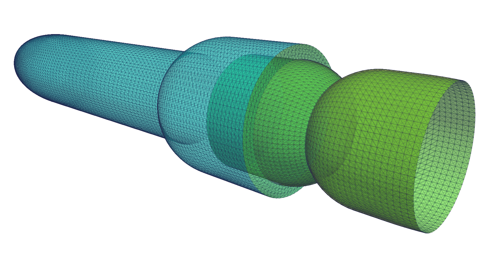
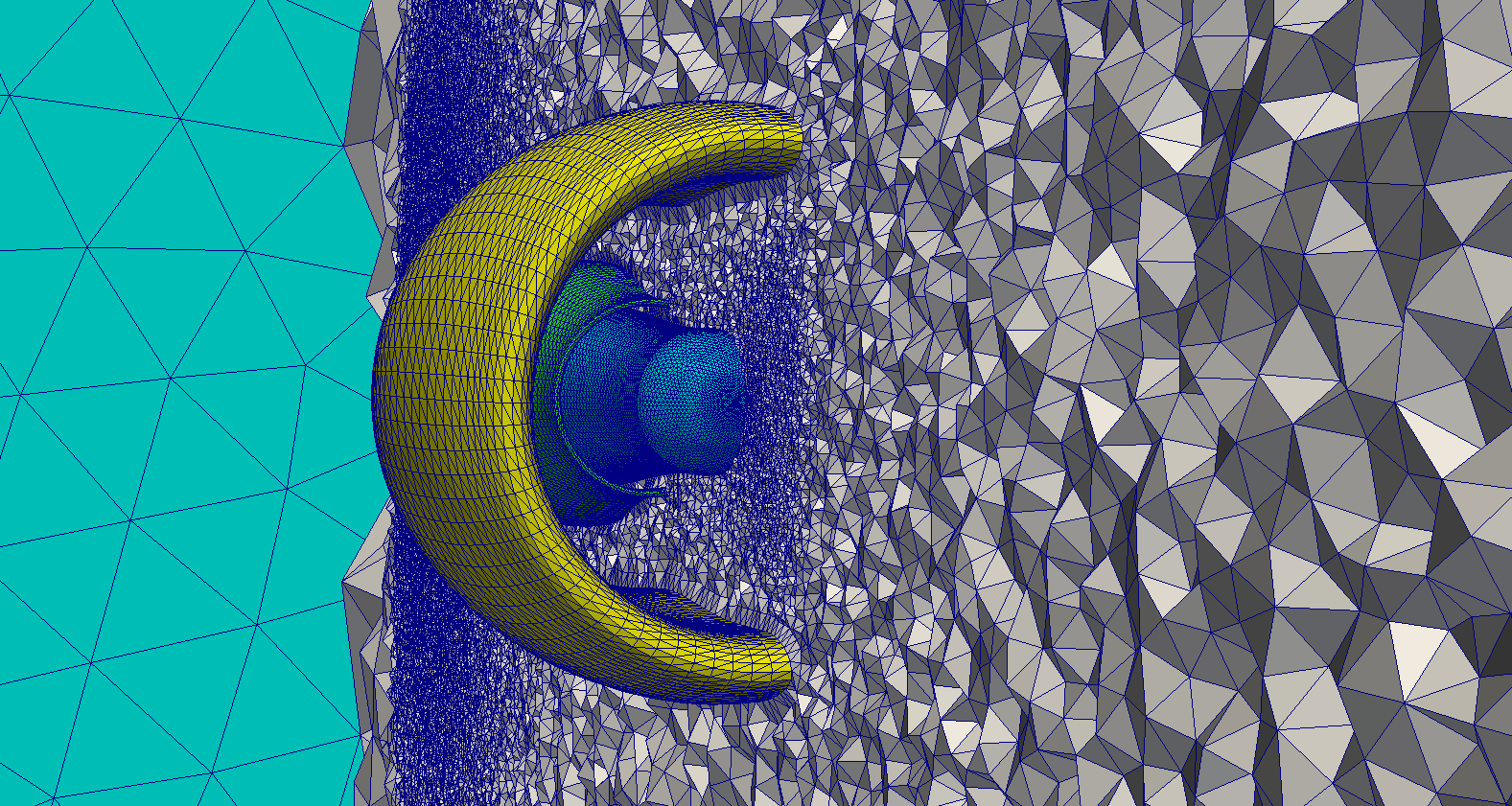
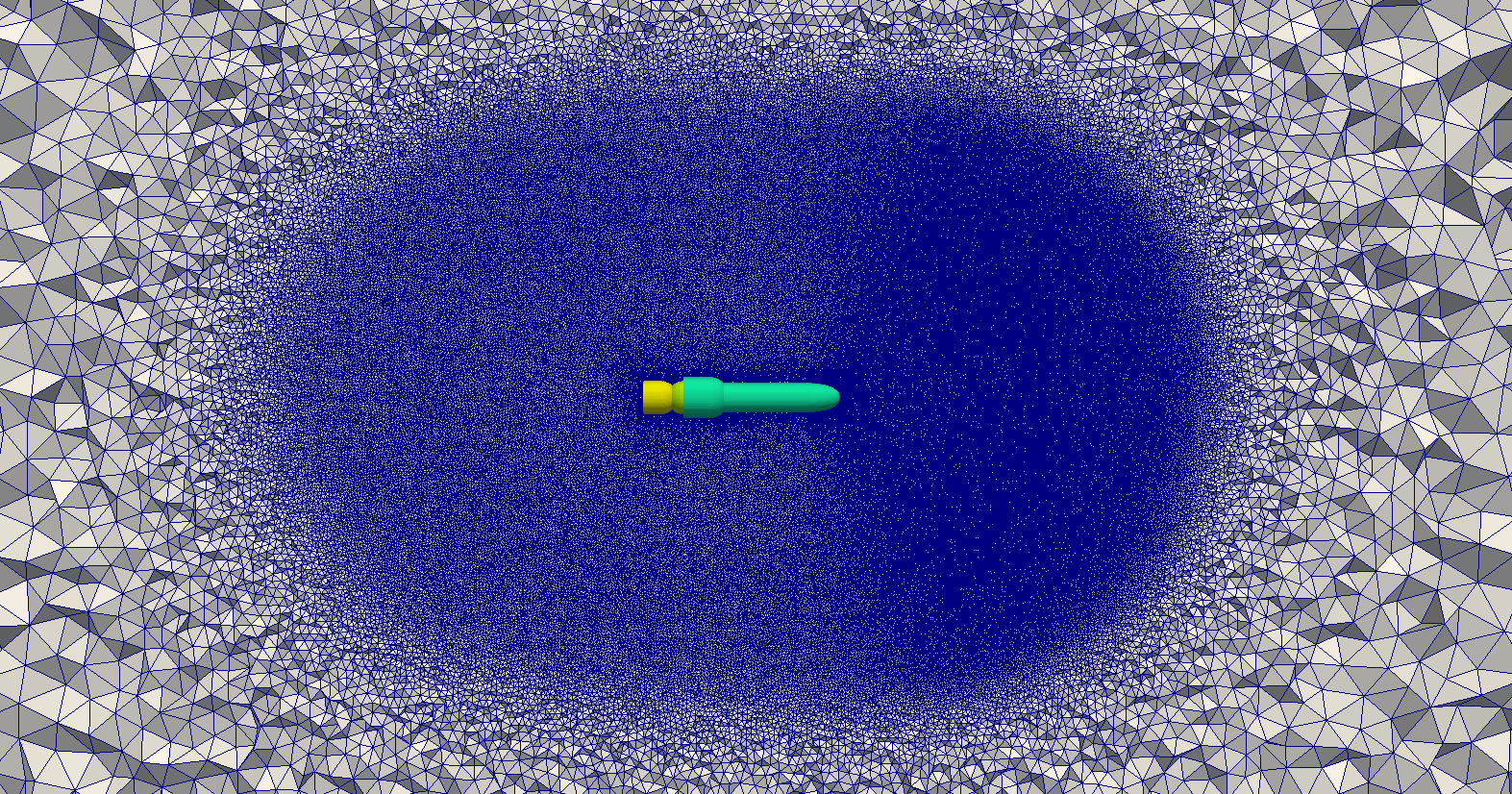
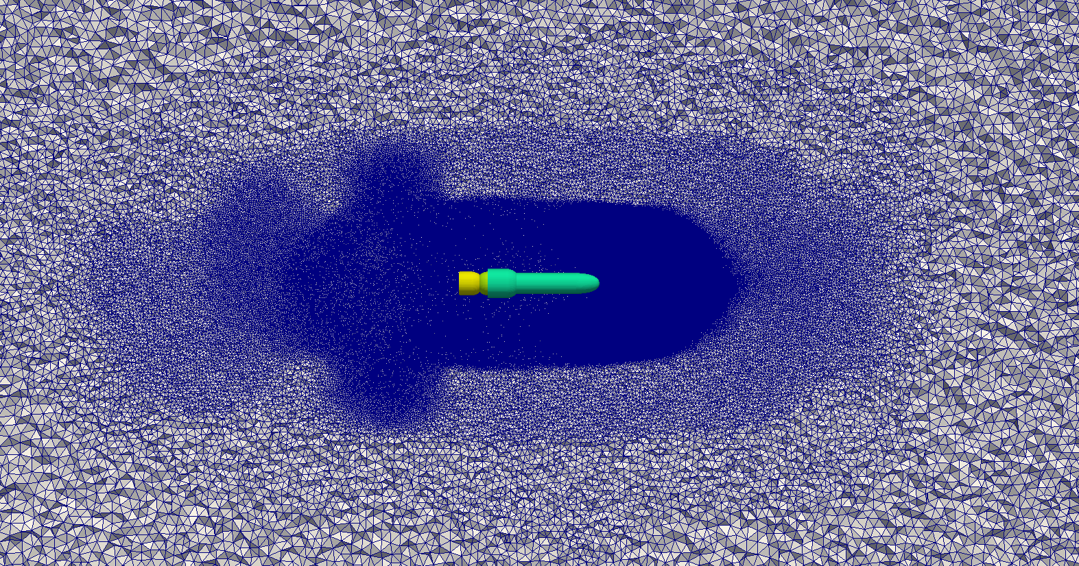
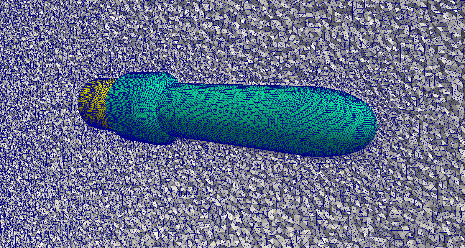
- Surface grid of a rocket with engine, nozzle and transparent internal data surfaces inside flow field.
- #points: 20228; #triangles: 40448
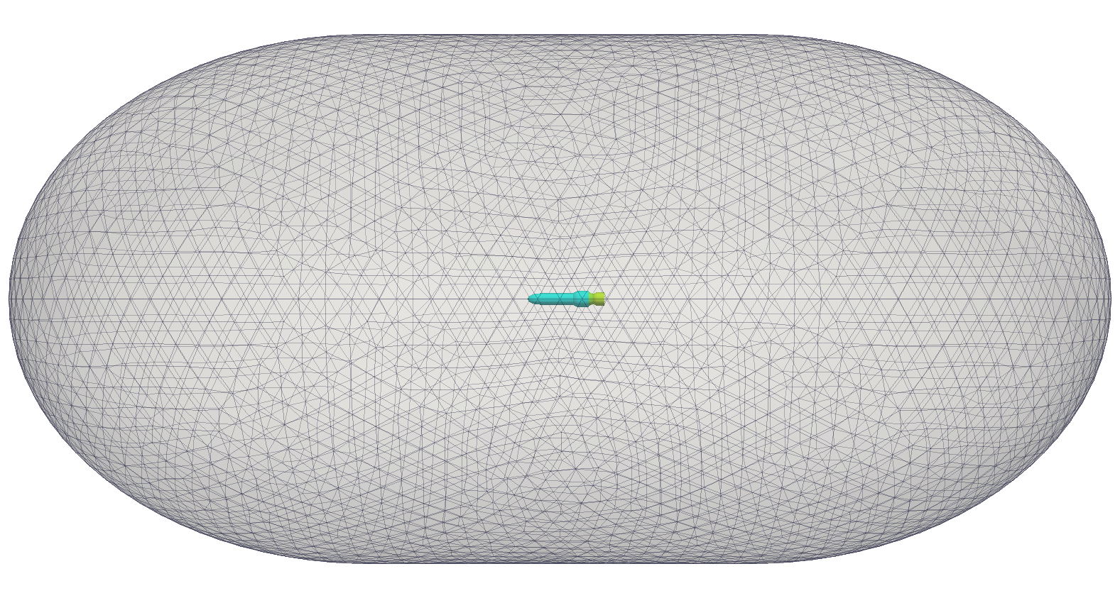
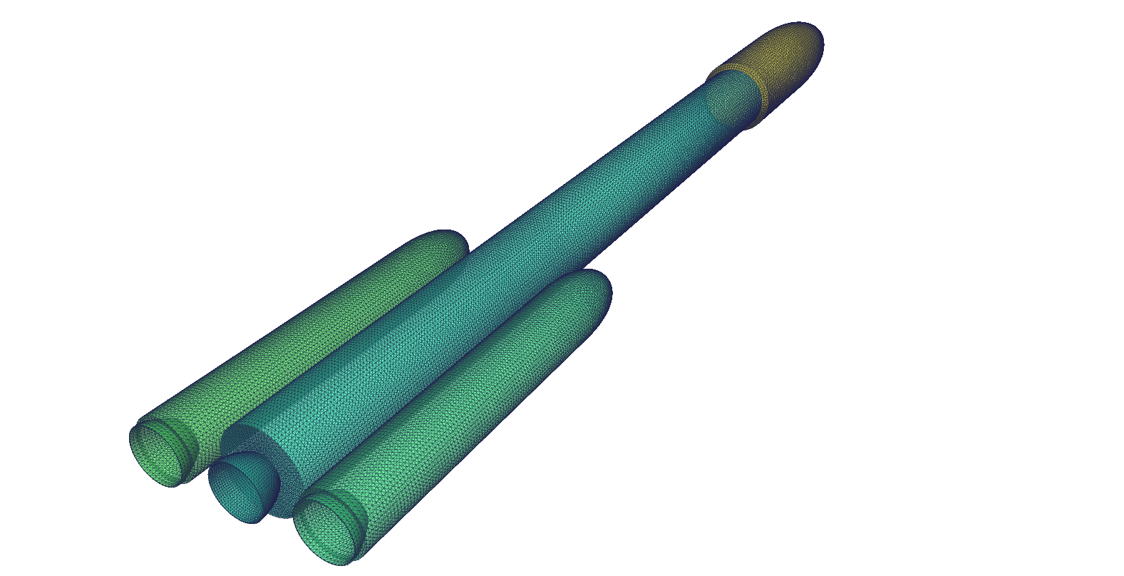
- Surface grid of a launch vehicle with solid boosters inside flow field (Lv2b).
- #points: 42020; #triangles: 84024
| Geometry | Software | cdfm | cdfn | mrecm | nqual | csmth | msmth | nsmth | angdfs | angqual | mdbs | |||||||||||
|---|---|---|---|---|---|---|---|---|---|---|---|---|---|---|---|---|---|---|---|---|---|---|
| Nacelle | CDT3D | 0.291 | 0.7 | 2 | 3 | 0.5 | 1 | 2 | 165° | 120° | 0 | |||||||||||
| AFLR | 0.50 | 0.7 | 2 | 3 | 0.5 | 1 | 2 | 165° | 120° | 0 | ||||||||||||
| Rocket | CDT3D | 0.20 | 0.7 | 2 | 3 | 0.5 | 1 | 2 | 165° | 120° | 0 | |||||||||||
| AFLR | 0.60 | 0.7 | 2 | 3 | 0.5 | 1 | 2 | 165° | 120° | 0 | ||||||||||||
| Lv2b | CDT3D | 0.234 | 0.7 | 2 | 3 | 0.5 | 1 | 2 | 165° | 120° | 0 | |||||||||||
| AFLR | 0.30 | 0.7 | 2 | 3 | 0.5 | 1 | 2 | 165° | 120° | 0 | ||||||||||||
| Case | Software | #Cores | %Slivers (w/o improv.) (x10-3) |
#Tets (w/ improv.)(M) |
Min/Max Angle (w/ improv.) (deg) |
Initial Grid (sec) |
Refinement (min) |
Improvement (min) |
Total (min) | |||||||||
|---|---|---|---|---|---|---|---|---|---|---|---|---|---|---|---|---|---|---|
| Nacelle | CDT3D | 1 | 3.74 | 43.65 | 13.57°/153.44° | 1.36 | 20.01 | 14.30 | 34.33 | |||||||||
| CDT3D | 12 | 3.70 | 42.85 | 12.06°/159.52° | 1.36 | 5.02 | 18.59 | 23.64 | ||||||||||
| AFLR | 1 | 2.97 | 43.16 | 7.00°/164.86° | 5.63 | 22.59 | 6.40 | 29.09 | ||||||||||
| Rocket | CDT3D | 1 | 2.96 | 118.41 | 9.39°/159.30° | 1.58 | 52.85 | 64.56 | 117.44 | |||||||||
| CDT3D | 12 | 2.95 | 119.06 | 9.21°/158.33° | 1.58 | 14.51 | 68.23 | 82.76 | ||||||||||
| AFLR | 1 | 3.05 | 123.13 | 5.58°/164.75° | 6.76 | 131.89 | 25.41 | 157.42 | ||||||||||
| Lv2b | CDT3D | 1 | 5.09 | 98.21 | 6.60°/159.68° | 5.45 | 41.57 | 94.63 | 136.29 | |||||||||
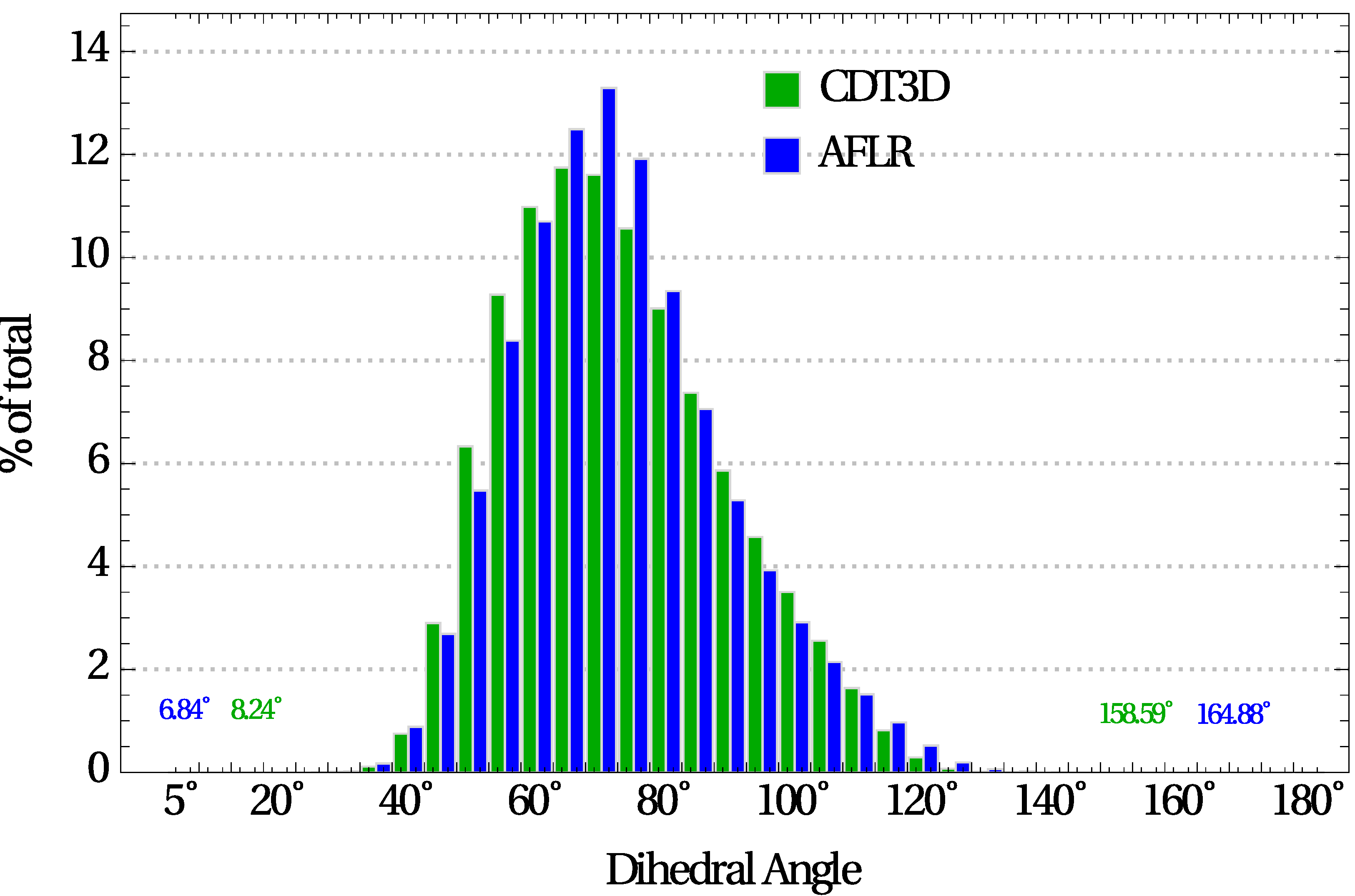
| CDT3D | 12 | 4.69 | 113.99 | 8.24°/158.59° | 5.45 | 12.92 | 62.36 | 75.37 | ||||||||||
| AFLR | 1 | 3.49 | 104.10 | 6.84°/164.88° | 16.97 | 98.24 | 18.51 | 117.03 | ||||||||||
more nacelle, rocket, and lv2b pg. 125-127
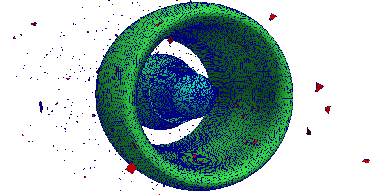
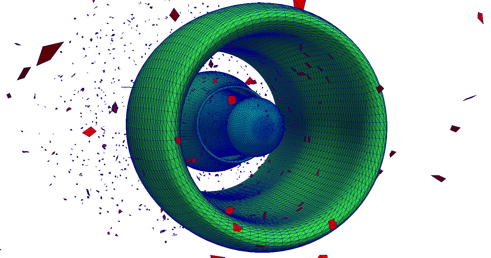
- Tetrahedral field cuts of the aircraft nacelle
- Detail views of tetrahedral field cuts of aircraft nacelle generated with CDT3D
- Tetrahedral field cuts of the rocket
Tetrahedral field cuts of the Lv2b
Element angle distribution (in 5-deg increments) of aircraft nacelle grids.
The dihedral angle extrema are reported for each method.
Element angle distribution (in 5-deg increments) after improvement of Rocket and Lv2b grids.
The dihedral angle extrema are reported for each method.
Slivers after the completion of refinement of the aircraft nacelle.
Red represents elements whose minimum dihedral angle is smaller than 2◦ or larger than 178◦.
